

Kinematic system for clamping semifinished products by means of pressing for sheet metal shaping panelling machines
a kinematic system and semi-finished product technology, applied in the direction of shafts, mechanical equipment, manufacturing tools, etc., can solve the problems of specific mechanical functions, unfavorable kinematic system work, and considerable reduction of the force delivered
- Summary
- Abstract
- Description
- Claims
- Application Information
AI Technical Summary
Benefits of technology
Problems solved by technology
Method used
Image

Examples
Embodiment Construction
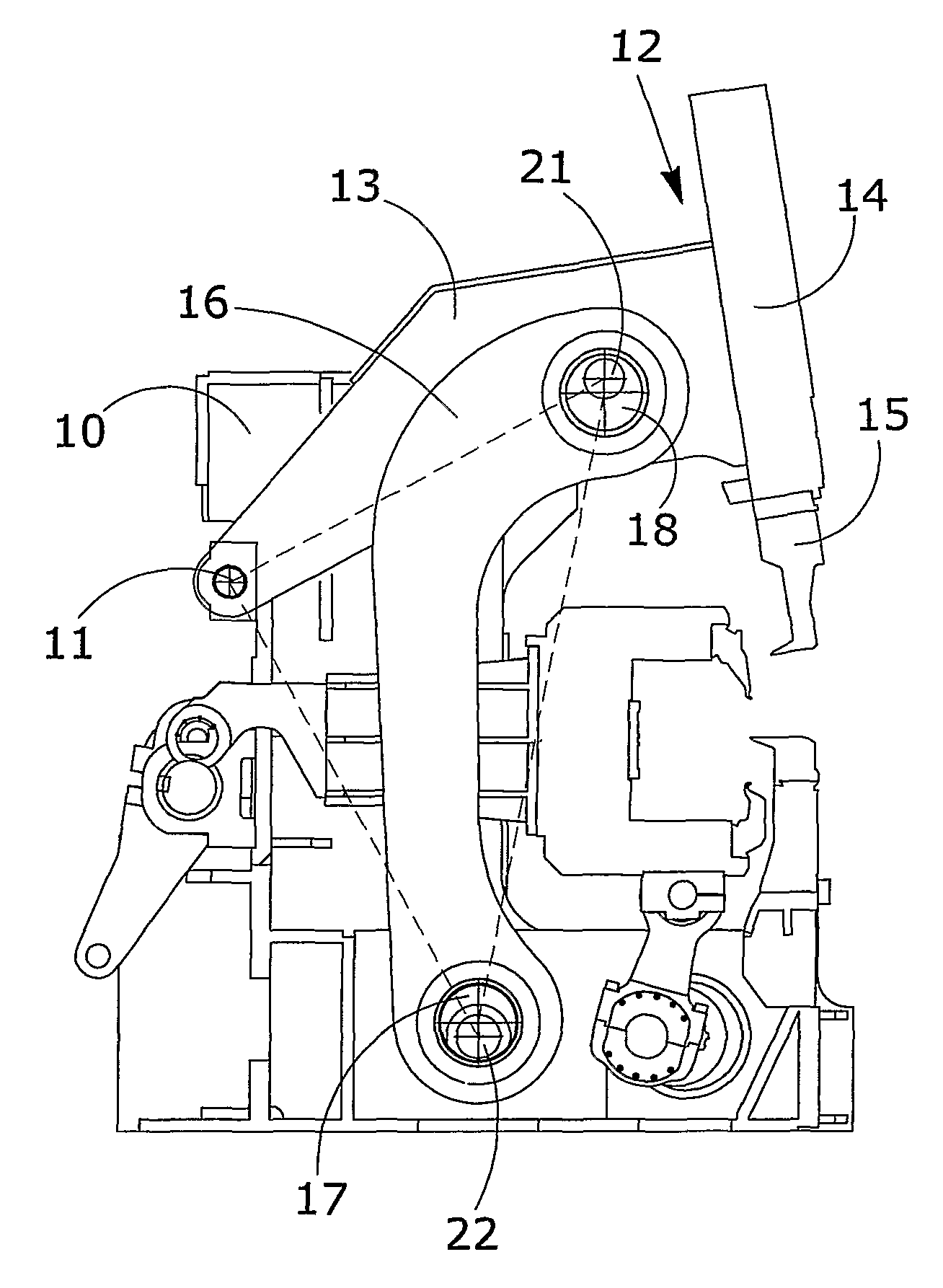
[0044]This invention proposes to provide a kinematic system for driving the pressing units of panelling machines that is able to eliminate or reduce the drawbacks described above, summarised in a reduced pressing force available when using auxiliary tools or when the pieces to be machines are particularly long or thick.
[0045]The invention proposes first of all to provide a kinematic system for driving the working units of a new design of panelling machine, which foresees the use of servomotors and epicycloidal or spheroidal reduction gears, that is to say motors with a high torque output (torque motors or similar) instead of traditional hydraulic actuators, for the movement of the pressing unit.
[0046]The servomotors and reduction gears in fact make it possible to achieve much higher performances than those of a hydraulic system, above all in the clamped rotor functioning typical of pressing operations.
[0047]This electrical control is made possible by a kinematic system for driving t...
PUM
| Property | Measurement | Unit |
|---|---|---|
| degrees of freedom | aaaaa | aaaaa |
| length | aaaaa | aaaaa |
| thickness | aaaaa | aaaaa |
Abstract
Description
Claims
Application Information