
Reluctance chain sensor and method of measuring the chain elongation

a technology of resistance chain and elongation, which is applied in the field of resistance chain sensor and the field of chain elongation, can solve the problems of inability to predict the failure the wear of the drive chain, and the operation of the drive unit,

Active Publication Date: 2017-06-06
IWIS ANTRIEBSSYST
View PDF8 Cites 4 Cited by
  • Summary
  • Abstract
  • Description
  • Claims
  • Application Information

AI Technical Summary

Benefits of technology

This patent aims to improve the monitoring of chain elongation caused by wear and tear in chain devices. A new sensor has been developed that includes a magnetically conductive yoke body with closely spaced teeth and a permanent magnet. This sensor is placed close to the chain so that it forms low magnetic resistance with the chain, allowing for accurate measurements. The yoke body is designed to be easily permeable to magnetic field, ensuring high magnetic conductivity. This new sensor and method of measuring chain elongation can help to improve the monitoring of chain devices and prevent damage caused by wear and tear.

Problems solved by technology

Drive chains are, in operation, subject to wear through the relative movement of the individual components in the chain hinge and to other various chain elongation factors, such as initial elongation, stretching, bearing slackness and bearing abrasion.
These wear and elongation factors result in an elongation of the chain and, in the end, lead to a failure of the drive unit.
Hence, chain wear and, consequently, the failure of the drive unit cannot be predicted with certainty.
The high investment cost of such fully automated machines and systems necessitates the constant use of the latter with the least possible number of inadvertent downtimes. Such inadvertent downtimes lead not only to direct financial losses but also to indirect problems, such as the interruption of the logistics chain and even an incapability of observing delivery times, and thus to further financial losses.
However, the use of wear-prone chain drives cannot be dispensed with in the foreseeable future, since there is no alternative that could be used for driving such industrial systems and for conveying products.
In addition, even minor wear of the drive chains in automated machines and industrial plants necessitates a manual readjustment of sequences of operations that are synchronized with the chain position.
However, a precondition for this is that, on the one hand, a chain tensioner is actually required or rotary position sensors can actually be used and, on the other hand, that these elements are then influenced by wear and chain elongation, respectively.
Hence, such methods must be calculated and adjusted with respect to the respective case of use and with respect to the effect of the measurement results and, consequently, these methods cannot be applied generically.
In addition, both said methods measure not only the direct wear-dependent chain elongation but also the wear of the chain wheels.
In addition, optical sensors are, in many cases of application, not suitable for practical use in driving and conveying systems, since the industrial surrounding conditions contribute, due to dust and dirt, to a possible failure or incorrect measurements of the optical sensors.
Inductive sensors exhibit, in addition to a switching sensitivity in the direction of measurement, also an inherent switching sensitivity perpendicular thereto, so that inductive sensors are not only sensitive to vibration but they also tend to execute incorrect measurements.

Method used


Image

  • Reluctance chain sensor and method of measuring the chain elongation
  • Reluctance chain sensor and method of measuring the chain elongation
  • Reluctance chain sensor and method of measuring the chain elongation

Examples


Embodiment Construction

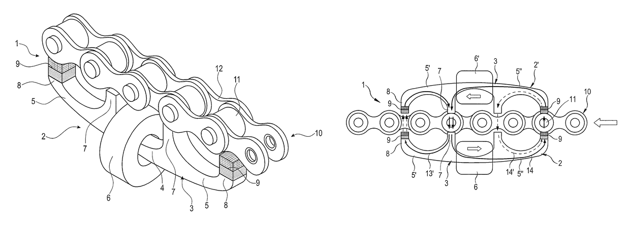
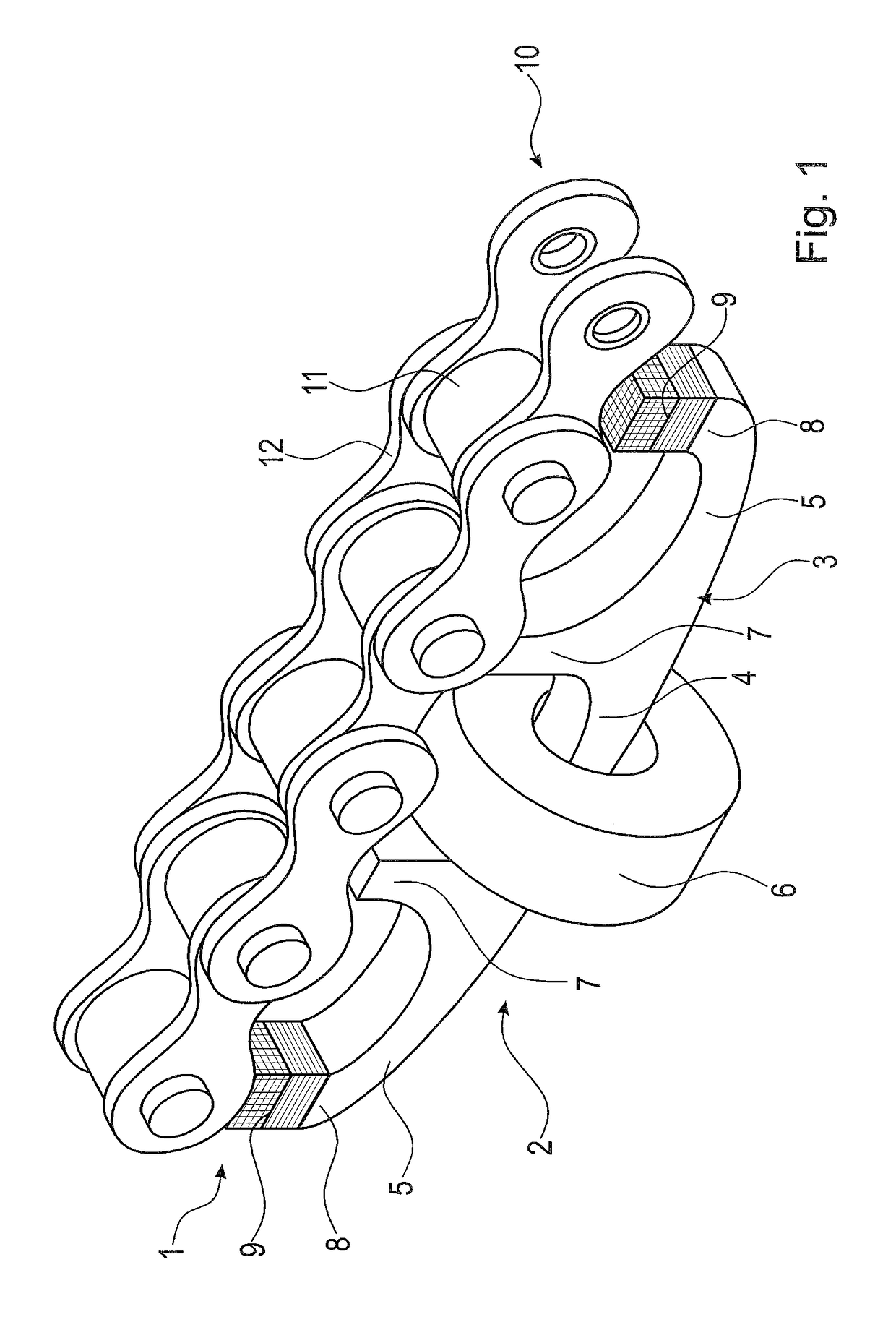
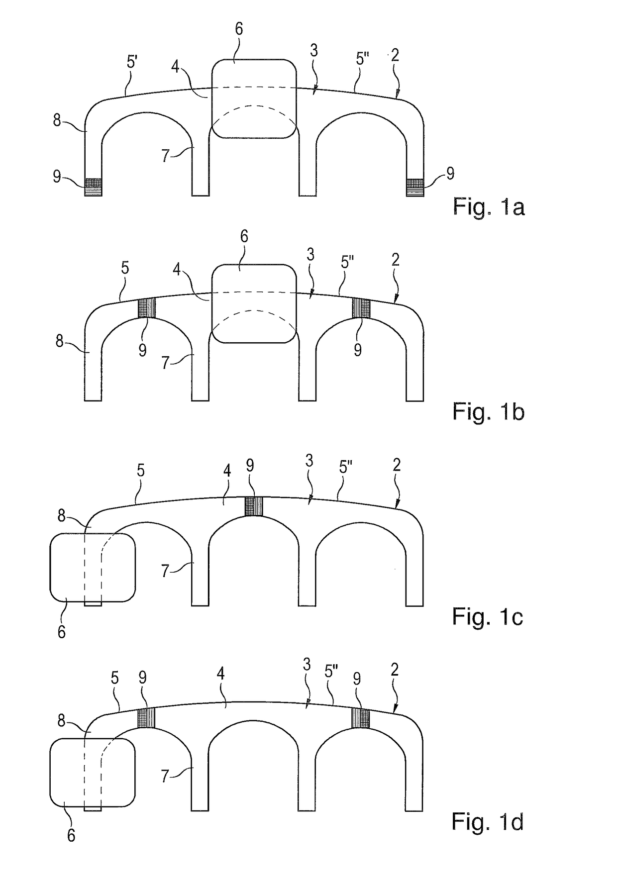
[0047]FIG. 1 shows a schematic representation of a chain sensor 1 according to the present invention with a first reluctance sensor 2 in a perspective view. The reluctance sensor 2 comprises a yoke body 3 consisting of a material that is magnetically conductive, i.e. permeable to magnetic fields, said yoke body 3 comprising in addition to a central leg 4 also two yoke legs 5 extending laterally of the central leg 4. The central leg 4 has arranged thereon a coil 6, which may extend over the entire length of the central leg 4 between the inner teeth 7 of the adjoining yoke legs 5. The yoke legs 5 have, in addition to the inner teeth 7 adjoining the central leg 4, also outer teeth 8 which are arranged on the respective outer ends of the yoke legs. The inner teeth 7 and the outer teeth 8 project relative to a central area of the yoke legs 5 in the direction of an articulated chain 10 so that a cavity is defined between the inner teeth 7 and the outer teeth 8 of the yoke legs 5 and the a...


PUM


Abstract

A chain sensor comprising at least one coil and a device for measuring the chain elongation comprising two chain sensors and a control unit, are provided. In addition, a method of measuring the chain elongation of a chain with two chain sensors arranged along the chain in spaced relationship with one another is provided. The chain sensor comprises at least one first reluctance sensor. The first reluctance sensor has a magnetically conductive yoke body comprising a central leg and two yoke legs extending laterally thereto. The yoke legs are each provided with at least two teeth, the teeth of the yoke legs being adapted to be arranged in closely spaced relationship with a chain. The first reluctance sensor includes at least one permanent magnet.

Description

CROSS-REFERENCE TO RELATED APPLICATION[0001]This application claims priority to foreign European patent application No. EP 14000520.8, filed on Feb. 13, 2014, and to foreign European patent application No. EP 15000167.5, filed on Jan. 21, 2015, the disclosures of which are incorporated by reference in their entireties.FIELD OF THE INVENTION[0002]The present invention relates to a chain sensor comprising at least one coil as well as to a device for measuring the chain elongation comprising two chain sensors and a control unit. In addition, the invention relates to a method of measuring the chain elongation of a chain with two chain sensors arranged along the chain in spaced relationship with one another.BACKGROUND[0003]Chain drives, in particular those based on roller chains, are used for the purpose of driving and conveying in industrial applications, wherein a plurality of chain strands being used in various fields of application. A chain drive unit normally comprises an endlessly ...

Claims


Application Information

Patent Timeline
Patent Type & Authority Patents(United States)
IPC IPC(8): G01B7/14G01D5/20G01M13/00
CPCG01D5/20G01D5/2013G01M13/00
Inventor SIRAKY, JOSEFKREISFELD, PETERMADLENER, FLORIAN
Owner IWIS ANTRIEBSSYST
Learn More