System and method for calibrating magnetic sensors in real and finite time

a magnetic sensor and real-time technology, applied in the field of real-time finite-time magnetic sensor calibration system, can solve the problems of inability to use these measures within systems which require a good level of accuracy, reliability and stability, and all the systems described above can be relatively expensive, so as to eliminate or reduce the drawbacks

Active Publication Date: 2020-11-17
GIPSTECH
View PDF16 Cites 0 Cited by
  • Summary
  • Abstract
  • Description
  • Claims
  • Application Information

AI Technical Summary

Benefits of technology

[0032]The problem solved by the present invention is to eliminate or reduce the drawbacks present in the existing traditional methods.
[0034]Within this aim, an object of the present invention is that of not requiring any assumption on the type of movements and rotations to which said device must be subjected during the estimation procedure.

Problems solved by technology

Systems based on the GPS, however, are not capable of operating inside buildings because normally the signal from the satellites is not able to penetrate inside closed places.
All the systems described above can be relatively expensive and require installation of supporting infrastructure within the enclosed space in which one wants to enable location services.
It is evident that the magnetic measurements obtained by said magnetometer must be as precise as possible otherwise the larger the measurement errors, the more unreliable the relative orientation determination between said reference system of the magnetometer and said external reference system, thus making unusable these measures within systems which require a good level of accuracy, reliability and stability.
In general, the magnetic field measurements obtained by means of a magnetometer are affected by different types of distortions which in fact make unusable the achievable measurement without first carrying out specially designed calibration procedures capable of removing such distortions.
For the sake of simplicity, it can be assumed that the measurement of the magnetic field obtainable by a magnetometer can be corrupted due to the presence of various ferromagnetic materials located in proximity of said magnetometer.
Although it may seem that the calibration applied for example in the factory can permanently solve the problem of measurement accuracy, in reality this is not true.
Ultimately, only one initial calibration of the magnetometer is insufficient to be able to obtain precise measurements of the magnetic field.
The first drawback is linked to the impossibility to define in advance in how much time an estimate of the calibration bias is obtainable, with a certain level of reliability.
From the above, it follows that the second drawback of these traditional methods, namely the need for the device hosting the magnetometer to undergo rotations of amplitude such as to cover sectors of the sphere (if in 3D) or circumference (if in 2D) which are significant for the purposes of allowing that the least squares algorithms or the resolution of systems of equations used by the methods are able to find a solution.
These traditional methods are insufficient for example in a classical context that sees as measuring instrument the use of a smartphone held in a user's pocket, which is subjected to excursions—understood in terms of angles of rotation for each of the three axes of measurement—that may not be sufficient to cover significant sectors of a circumference (or a sphere) and then to allow said traditional methods to determine the bias.
Or these excursions may be such that the time required for the determination of the solution is unacceptable for the purposes of the overall functioning of the system.
Ultimately, the commonly used geometric approach made on these traditional methods does not guarantee that under certain conditions it is possible to find a solution to the problem and does not guarantee that, if the solution is admissible, the latter can be found in a set time.
However, even this method does not guarantee that the convergence of the algorithm for estimating the bias is obtained in a finite time but only asymptotically.
All these conventional solutions are not satisfactory, however, as explained above.

Method used


Image

  • System and method for calibrating magnetic sensors in real and finite time
  • System and method for calibrating magnetic sensors in real and finite time
  • System and method for calibrating magnetic sensors in real and finite time

Examples


Embodiment Construction

[0041]Further features and advantages of the invention will become apparent from the description of preferred embodiments, which are not exclusive or limiting, of a method for the real-time and finite-time calibration of magnetic sensors according to the invention, illustrated only by way of indication and not by way of limitation in the accompanying drawings, in which:

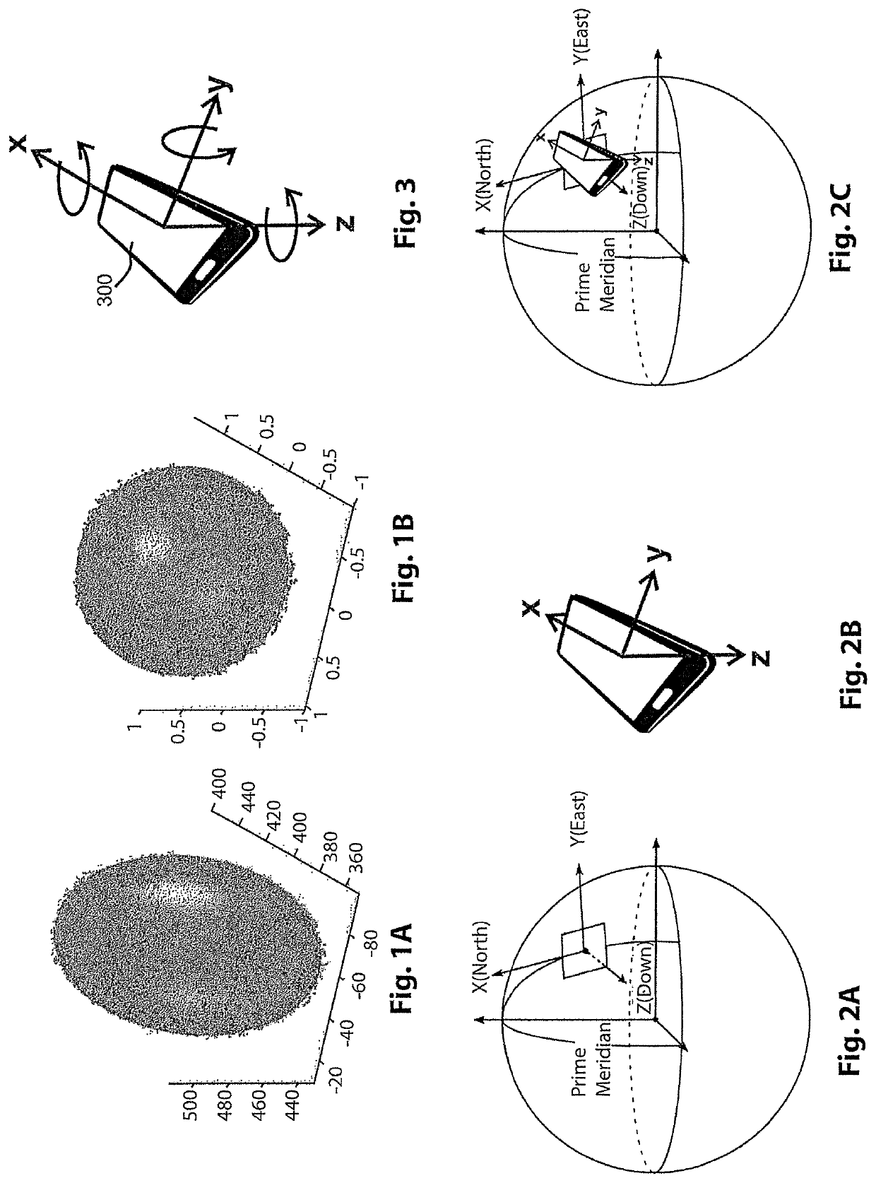
[0042]FIGS. 1A and 1B show the locus of the magnetic field measurements acquired respectively by using a uncalibrated magnetometer and a calibrated magnetometer.

[0043]FIGS. 2A, 2B, 2C illustrate the two reference systems. In particular, FIG. 2A shows a known reference system, external to the sensor, and known as the NED (North, East, Down) reference system. FIG. 2B shows a reference system fixed to the device which carries out the magnetic and the angular rotation measurements. FIG. 2C shows said overlapped reference systems highlighting the angles that can be determined between said systems.

[0044]FIG. 3 shows the axe...


PUM


Abstract

The present invention relates to a calibration method of magnetic sensors, for removing from the measurements the so-called “bias” and obtaining the actual measurement of the magnetic field. This method, in addition to measurements of such magnetic sensors, uses measurements of angular rotation sensors available in various types of commercial devices including smartphones. The present invention also relates to a corresponding system for determining the instantaneous real time orientation and / or position of a mobile device with respect to a magnetic field.

Description

[0001]The present invention relates to a method for real and finite time calibration of magnetometers.[0002]In particular, the present invention relates to a method for estimating the value of the corrective three-dimensional vector, or better known as “bias”, necessary to obtain the actual magnetic measurement from measurements obtained by conventional magnetometers and angular rotation sensors available to within various types of commercial devices including smartphones. The present invention especially concerns calibration of magnetometers using the magnetic field measurements and the angular rotation obtainable for example by the gyroscopes, present inside navigation systems.STATE OF PRIOR ART[0003]To allow the use of navigation and tracking systems the GPS system is currently known and used. Systems based on the GPS, however, are not capable of operating inside buildings because normally the signal from the satellites is not able to penetrate inside closed places. To enable loc...

Claims


Application Information

Patent Timeline
Patent Type & Authority Patents(United States)
IPC IPC(8): G01C17/38G01C17/04G01R35/00G01C25/00G01C21/10G01R33/00
CPCG01R35/005G01C25/005G01C21/10G01C17/38G01C17/04G01R33/0017
Inventor D'ALFONSO, LUIGID'AQUILA, GAETANOFEDELE, GIUSEPPE
Owner GIPSTECH
Why Eureka
Try Eureka