Drive Unit for Trailers and Caravans

a technology for driving units and caravans, applied in steering parts, vehicle maintenance, transportation and packaging, etc., to achieve the effects of good maneuverability, great friction, and great traction for

Inactive Publication Date: 2009-12-17
MOVER TECH
View PDF7 Cites 27 Cited by
  • Summary
  • Abstract
  • Description
  • Claims
  • Application Information

AI Technical Summary

Benefits of technology

[0015]When, as stated in claim 1, the drive unit is equipped with a coupling device which comprises first and second coupling parts, said first coupling part being arranged on the chassis of the drive unit, and said second coupling part being arranged on the hitch triangle in a position disposed behind both the normal hitch coupling and the nose wheel suspension, an advantageous weight distribution is achieved between main wheel and drive unit. The crawler sections provide a large surface contact and thereby great friction between the drive unit and the support, so that it is possible to transfer great traction forces to the trailer or the caravan. Further, the crawler sections give good maneuvering options in cooperation with the steering and maneuvering means and the incorporated energy supply.
[0016]When, as stated in claim 1, the coupling device is constructed so as to comprise a bracket secured to the top of the chassis, to which the first coupling part is secured, as well as a second bracket arranged on the hitch triangle, to which the second coupling is secured, and the coupling parts are adapted to engage each other, it is ensured that the drive unit may be coupled with a trailer or a caravan in a simple manner without having to make radical changes of the existing structure, so that the mounting may be carried out by others than skilled persons.
[0018]When, as stated in claim 1, the bracket for the hitch triangle is adapted to comprise the second coupling part as well as two fixing brackets for fixing to the side members of the hitch triangle as well as an adjustable pipe profile arranged between the fixing brackets, and the second coupling, a coupling element is achieved, which is easily mounted and which is capable of absorbing pressure and torsion impacts applied to the triangle by the drive unit.

Problems solved by technology

The crawler sections provide a large surface contact and thereby great friction between the drive unit and the support, so that it is possible to transfer great traction forces to the trailer or the caravan.

Method used


Image

  • Drive Unit for Trailers and Caravans
  • Drive Unit for Trailers and Caravans
  • Drive Unit for Trailers and Caravans

Examples


Embodiment Construction

[0032]Exemplary embodiments shown in FIG. 1, FIG. 2, FIG. 3, FIG. 4, FIG. 5, FIG. 6 and FIG. 7, respectively, will be described below.

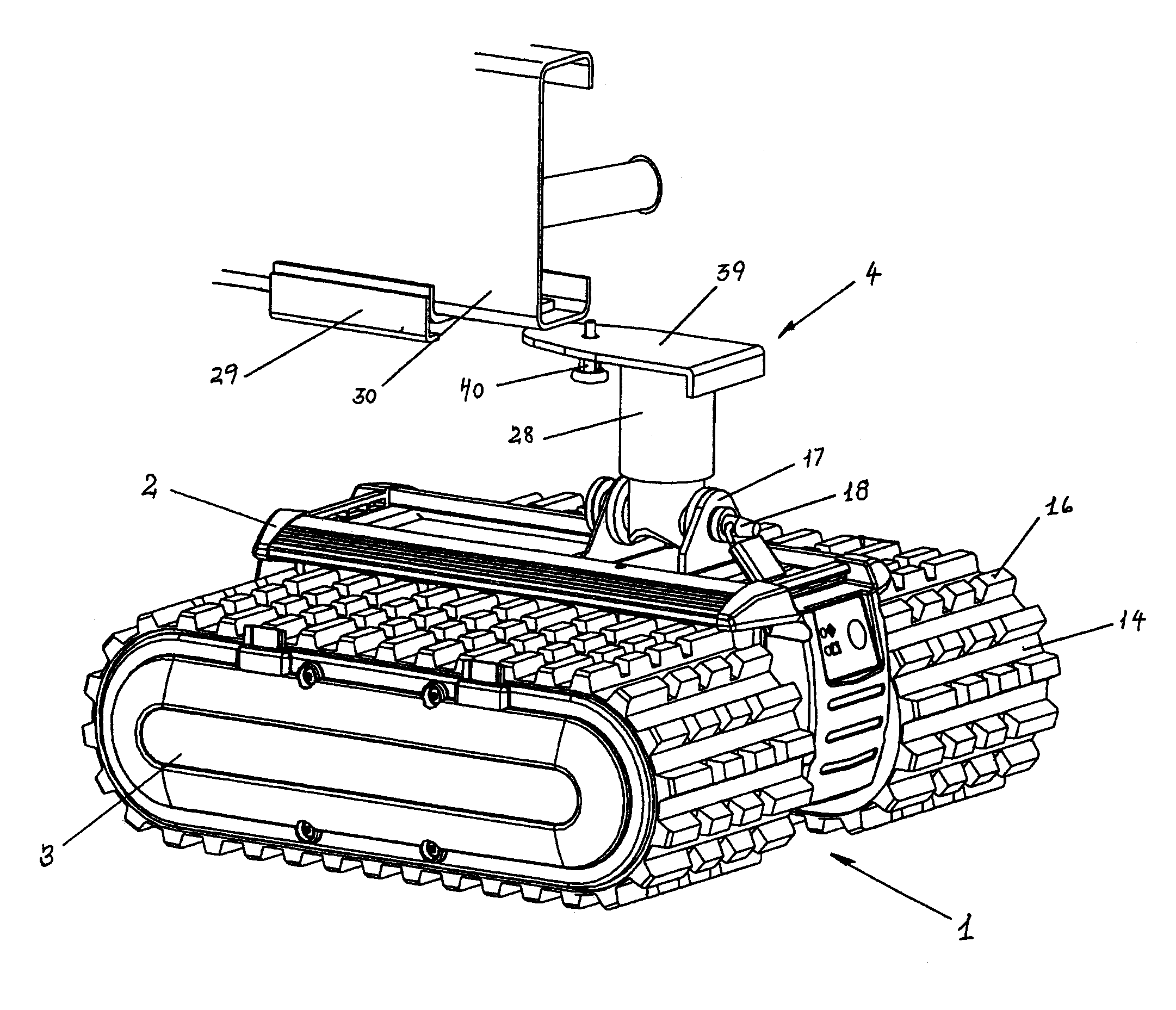
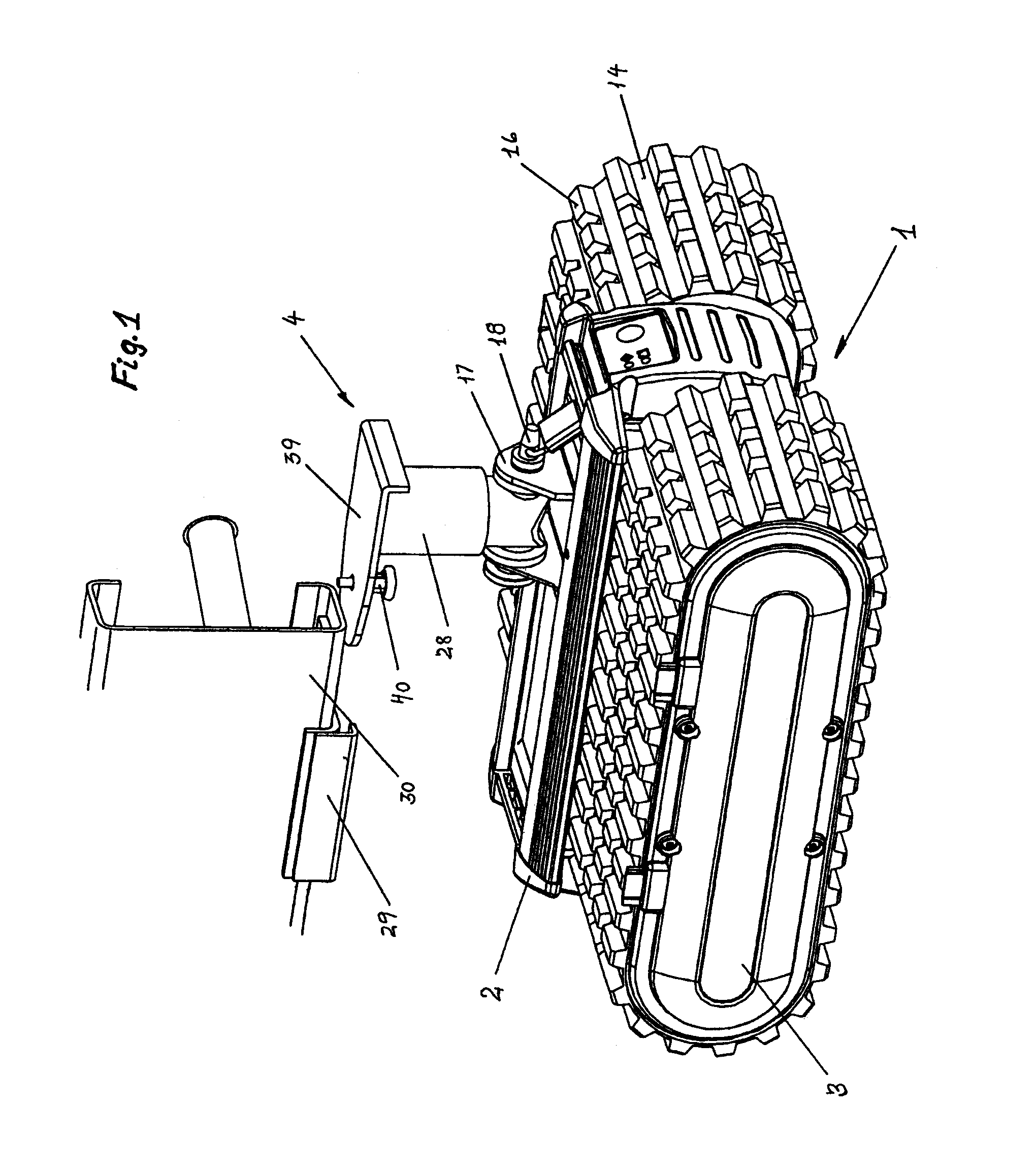
[0033]FIG. 1 shows how the drive unit 1 is constructed, and the main components which are included. The drive unit 1 is based on a chassis 2 made of a profile on which crawler sections 3, a coupling device 4 for coupling to the hitch triangle 30 of the trailer or of the caravan, as well as means for steering and maneuvering the drive unit may be mounted. The profile is dimensioned to be capable of supporting the load which is normally applied to the hitch coupling. The profile may be extruded, but may also be welded. The material may be aluminum or steel.

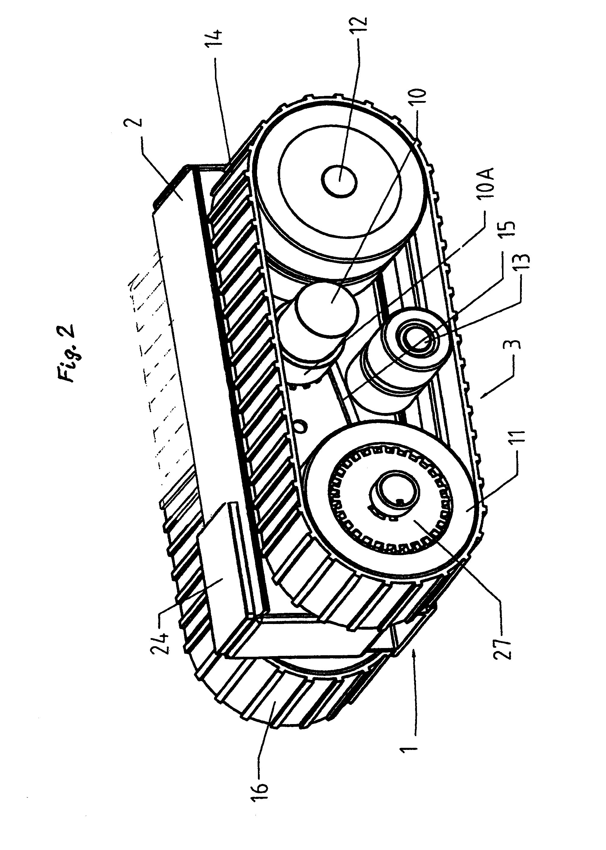
[0034]FIG. 2 shows that the crawler sections 3 are mounted on each side of the chassis 2. The crawler sections 3 comprise a motor 10 with a gear 10a which is in engagement with a driving wheel 11, an idling wheel 2, at least one support wheel 13 and a crawler belt 14 via a drive connection 15. As show...


PUM


Abstract

When, according to the invention, a drive unit for trailers or caravans is arranged such that it comprises a chassis (2) with crawler sections (3), a coupling device (4) having first and second coupling parts (28, 29), said coupling parts (29) being arranged on the hitch triangle (30) behind the normal hitch coupling and behind the nose wheel, and the drive unit additionally comprises means for steering and maneuvering the unit, a good weight distribution is achieved between main wheel and drive unit, so that it is easy to control the placing of the trailer or of the caravan, without having to worry about the risk of colliding with the neighbour or damaging one's own vehicle.

Description

THE PRIOR ART[0001]The invention relates to a motorized, maneuverable drive unit having crawler sections, said drive unit being intended to be mounted on the hitch triangle of trailers and caravans in particular, said hitch triangle being equipped with a hitch coupling and a nose wheel, wherein the drive unit comprises a chassis with a coupling device having a first coupling part and a second coupling part, said first coupling part being arranged on the chassis, and said second coupling being suitable for mounting in a secured manner on the hitch triangle behind the hitch coupling and the nose wheel, and wherein the drive unit also comprises an energy supply and means for steering and maneuvering the drive unit, and wherein the coupling device additionally comprises a bracket which is arranged on the chassis, and to which the first coupling part is secured, as well as a second bracket which is suitable for mounting on the hitch triangle, and to which the second coupling part is secu...

Claims


Application Information

Patent Timeline
Patent Type & Authority Applications(United States)
IPC IPC(8): B62D49/00
CPCB60S9/215B60S13/00B62D55/06B62D51/007B62D49/007
Inventor WESTERDAARD, KNUD ERIK
Owner MOVER TECH
Why Eureka
Try Eureka