Coupling mechanism for headrest of vehicle seat

a technology for vehicle seats and coupling mechanisms, which is applied in vehicle components, pedestrian/occupant safety arrangements, vehicle arrangements, etc., can solve the problems of short distance between the headrest and the headrest, difficulty in compensating for lack of distance, and restricted cushion design, etc., and achieves the effect of simple configuration

Active Publication Date: 2009-12-17
TS TECH CO LTD +1
View PDF22 Cites 24 Cited by
  • Summary
  • Abstract
  • Description
  • Claims
  • Application Information

AI Technical Summary

Benefits of technology

[0004]The coupling mechanism of the prior art is disposed substantially at the backside of a cushion of the backrest, and thus the cushion performance may be lowered. That is, the coupling mechanism is provided at a position overlapping the vehicle seat occupant in the front-back direction, and thus the cushion design is restricted.
[0006]It is hence an object of the invention to provide a coupling mechanism for a headrest capable of amplifying the small moving amount of the movable member and transmitting the movement to the headrest.
[0007]It is another object of the invention to provide a coupling mechanism for a headrest capable of amplifying the moving amount of the movable member with a simple configuration.
[0008]It is still another object of the invention to provide a coupling mechanism for a headrest not interfering with the cushion of the backrest substantially.

Problems solved by technology

That is, the coupling mechanism is provided at a position overlapping the vehicle seat occupant in the front-back direction, and thus the cushion design is restricted.
The movable member in the prior art is narrow in its movable range, and the distance of moving the headrest forward is short, and means for compensating for lack of distance was difficult.

Method used


Image

  • Coupling mechanism for headrest of vehicle seat
  • Coupling mechanism for headrest of vehicle seat
  • Coupling mechanism for headrest of vehicle seat

Examples


Embodiment Construction

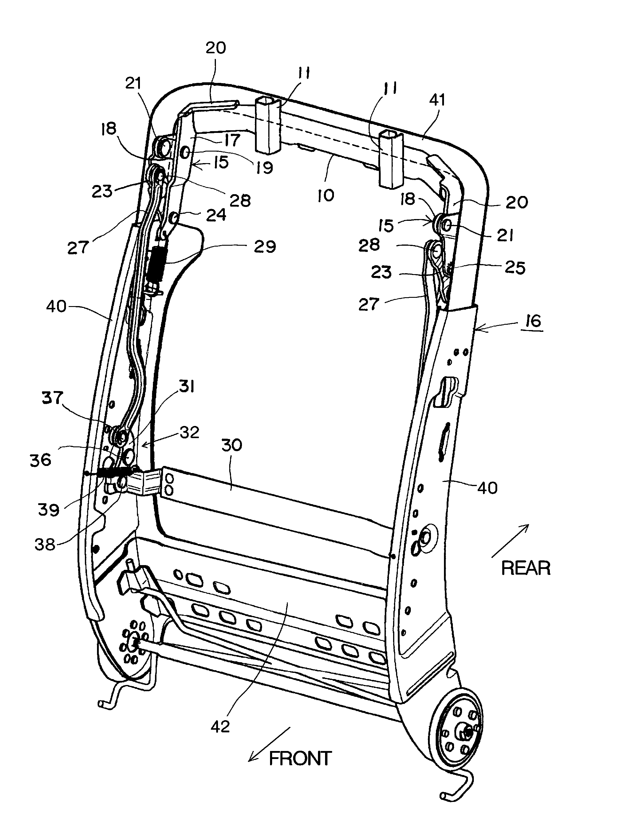
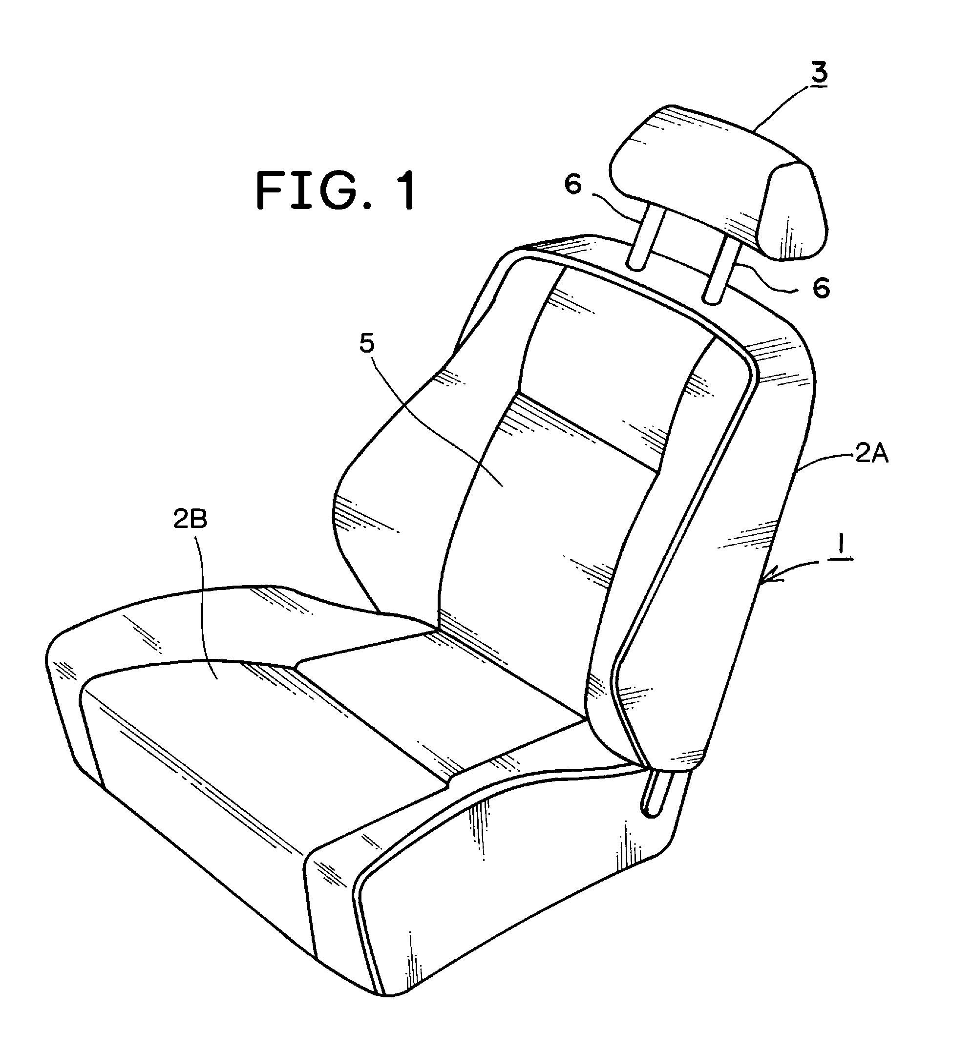
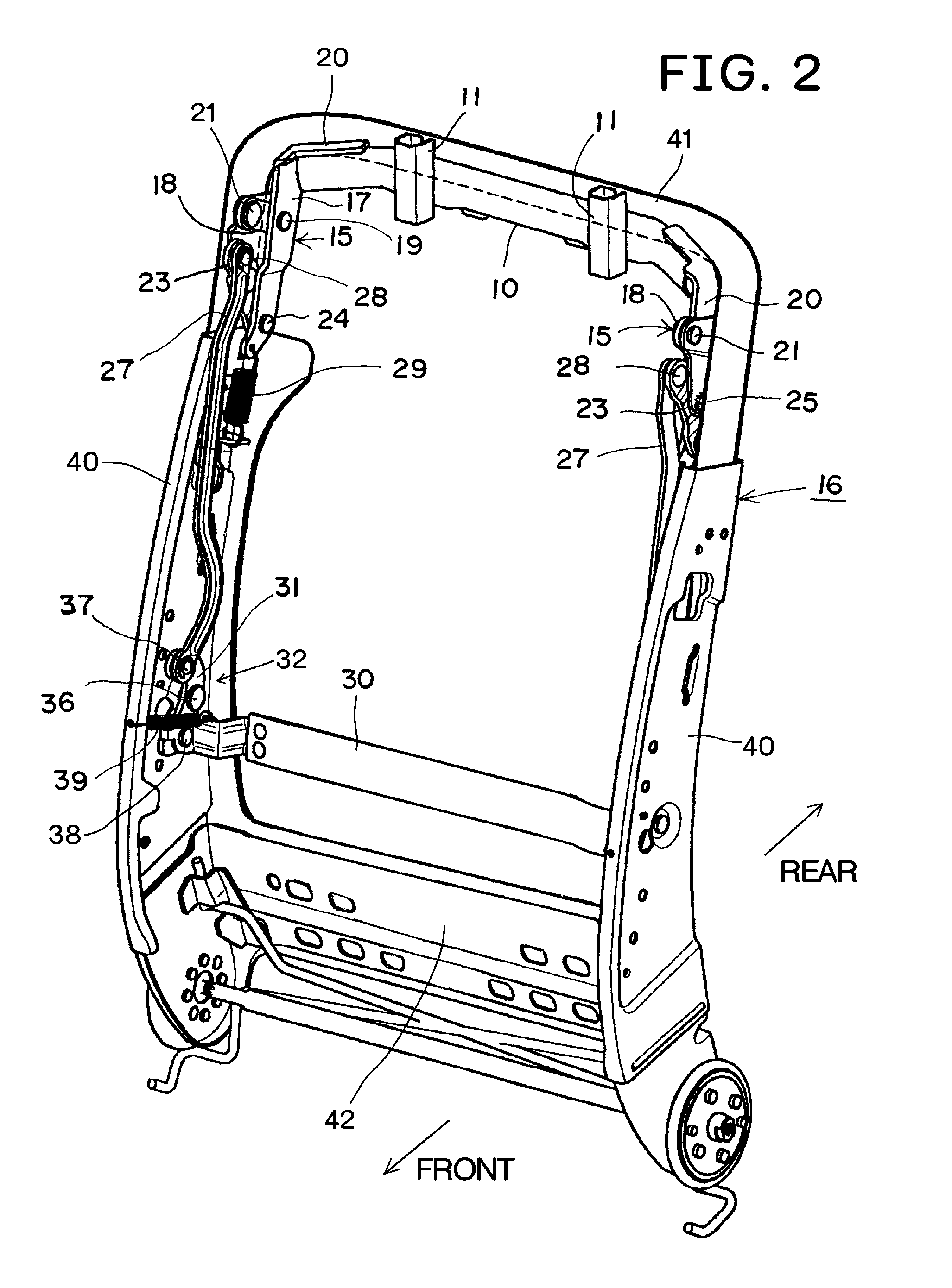
[0017]An embodiment of the invention will be described with reference to the accompanying drawings. A vehicle seat 1 of the invention has a backrest 2A, a seat bottom 2B, and a headrest 3 provided in an upper part of the backrest 2A. A backrest frame 16 of the backrest 2A has a square frame shape, including a pair of side frames 40, an upper frame 41, and a lower frame 42.

[0018]Near the upper frame 41, an upper movable member 10 movable laterally to the backrest frame 16 is disposed. Vertical pillar supports 11 for inserting the lower parts of pillars 6 of the headrest 3 are fixed in the movable member 10. The pillars 6 are supported by the pillar supports 11 so as to be adjustable in height.

[0019]Both right and left sides of the upper movable member 10 are attached to the backrest frame 16 by way of an individual upper link mechanism 15. Each upper link mechanism 15 has a long first link 17, an arm 18, and a second link 23 as shown in FIGS. 2, 3 and 7. The end part of the upper mov...


PUM


Abstract

A vehicle seat of the invention has an upper movable member (10) supporting a headrest (3), a lower movable member (30) provided inside a backrest, and a coupling mechanism for coupling the upper movable member and the lower movable member. The coupling mechanism includes an upper link mechanism (15) positioned in an upper part of a side frame (40) and coupled to the upper movable member, a lower link mechanism (32) positioned in a lower part of the side frame and coupled to the lower movable member, and a rod (27) extending along the side frame and coupling the upper link mechanism and the lower link mechanism. The upper link mechanism amplifies a backward moving amount of the lower movable member, and moves the headrest forward.

Description

TECHNICAL FIELD[0001]The present invention relates to a coupling mechanism for a headrest of a vehicle seat, and more particularly to a coupling mechanism for moving the headrest forward when a forward external force acts on a car body as a result of rear end collisions or the like.BACKGROUND ART[0002]Conventionally, there is known a vehicle seat having a headrest provided in a backrest, a movable member provided inside of the backrest, and a coupling mechanism for coupling the headrest and the movable member mechanically, in which when a vehicle seat occupant moves backward relatively to the vehicle seat due to rear collisions or the like, the movable member is pushed by the occupant to move backward, and the backward movement of the movable member moves the headrest forward by way of the coupling mechanism.[0003]Patent document 1: JP Appln. Laid-Open No. 10-119619DISCLOSURE OF THE INVENTION[0004]The coupling mechanism of the prior art is disposed substantially at the backside of a...

Claims


Application Information

Patent Timeline
Patent Type & Authority Applications(United States)
IPC IPC(8): B60N2/42B60N2/48
CPCB60N2/4885B60N2/4805B60N2/42727B60N2/888B60N2/806
Inventor NIITSUMA, KENICHINEGISHI, HIROOKITANABE, JINICHISANO, KOJIUNO, KOJITERAUCHI, TATSUYAMATSUMOTO, TOMOKI
Owner TS TECH CO LTD
Why Eureka
Try Eureka