Lower cushioning structure and package cushioning structure for display panel

a display panel and cushioning structure technology, applied in the field of article packaging technologies, can solve the problems of time-consuming, time-consuming, and inability to make the spacing between the display panels too small, and achieve the effects of low cost, poor cushioning effect, and reduced cushioning

Active Publication Date: 2014-05-13
TCL CHINA STAR OPTOELECTRONICS TECH CO LTD
View PDF17 Cites 20 Cited by
  • Summary
  • Abstract
  • Description
  • Claims
  • Application Information

AI Technical Summary

Benefits of technology

[0010]A primary objective of the present invention is to provide a lower cushioning structure and a package cushioning structure for a display panel, which have a low cost and can provide satisfactory cushioning for the display panel.
[0020]To achieve the aforesaid objective, the present invention further provides a package cushioning structure for a display panel, comprising: first cushions to be disposed at corners of the display panel; and second cushions to be disposed at sides of the display panel, wherein: each of the first cushions is formed with first recesses for receiving a corner of the display panel; each of the second cushions is formed with second recesses for receiving a side of the display panel; and the first cushions have a better cushioning performance than the second cushions.
[0026]The present invention has the following benefits. As compared to the conventional package cushioning structures for a display panel which have either a high cost or a poor cushioning effect, the package cushioning structure and the lower cushioning structure of the present invention use two kinds of cushions having different cushioning performances. Specifically, the first cushions have a small hardness or high cushioning performance, so they are adapted to be disposed at corners of the display panels to effectively protect the corners of the display panels from being deformed when the package drops to the ground or is impacted. On the other hand, to solve the problem that an excessive compression of the first cushions having a low density or high cushioning performance might cause collisions between the display panels, the second cushions having a poorer cushioning performance or a higher hardness are disposed at sides of the display panels. Thus, when the display panels move close to each other due to impact, the second cushions can provide an effective separation effect by virtue of the high hardness thereof, thus preventing damage caused by collisions between adjacent display panels. Meanwhile, owing to the effect of the second cushions, spacings between the display panels can be made to be small enough without having to worry about occurrence of collisions between the display panels. In this way, more display panels can be put in a unit volume to save both the transportation cost and the package cost.
[0027]Additionally, in an embodiment of the present invention, the first cushions are EPE cushions and the second cushions are corrugated cardboard cushions. This embodiment has advantages of both the low-density EPE which has a better cushioning performance and the corrugated cardboard which has a higher hardness than the low-density EPE. Specifically, by folding a corrugated cardboard into a structure that can separate different display panels from each other and cushion the display panels and then attaching the structure onto a side of another corrugated cardboard or a paper mount to fix the display panels, two adjacent display can have a small spacing therebetween without colliding with each other; and by forming the cushioning structure of the low-density EPE, the cushioning structure can provide a better cushioning effect for the two lower corners of each display panel. Thus, even when the display panel drops to the ground, the corners thereof will not be deformed. Moreover, use of raw materials can be reduced in the whole cushioning structure.
[0028]Additionally, in another embodiment of the present invention, the second cushions formed by a folded corrugated cardboard and the first cushions formed of EPE may be spaced apart from but not adjoin each other. Through use of the corrugated cardboard and EPE in combination, both a better cushioning effect and a small spacing between display panels can be obtained. In this way, more display panels can be put in a unit volume to save both the transportation cost and the package cost.

Problems solved by technology

Although this solution is environmental friendly, it has the following disadvantages: the corrugated cardboard is relatively stiff; when the carton drops onto the ground, corners of the display panels in contact with the corrugated cardboard are liable to deformation; furthermore, because the manufacturing process is complex and entirely relies on manual operation, it is time- and labor-consuming.
However, as the cushioning structure is made of the low-density EPE, spacings between the display panels cannot be made to be too small: because of the soft nature of EPE, a too small spacing would cause the display panels to collide with each other.
However, because the paper mount 320 has a certain thickness, so it occupies a certain amount of space in the width direction; furthermore, the paper mount 320 is more expensive than the cardboard, so this solution has the disadvantages of both Solution I and Solution II described above.
However, it is not environmental friendly; especially, because use of EPS is prohibited in some countries, this may have an influence on export of products adopting such a package cushioning design.
Additionally, EPS has a poorer cushioning performance than the corrugated cardboard and EPE.
However, this solution has the following disadvantages: use of the high-density cushioning structure 510 and the low-density cushioning structure 520 in combination leads to a complex production process that comprises too many steps, which drives the labor cost to be much higher; moreover, the high-density EPE structure 510 is costly, which makes the cost of the whole cushioning structure relatively high.

Method used


Image

  • Lower cushioning structure and package cushioning structure for display panel
  • Lower cushioning structure and package cushioning structure for display panel
  • Lower cushioning structure and package cushioning structure for display panel

Examples


Embodiment Construction

[0038]Reference will now be made to the drawings to describe preferred and exemplary embodiments of the present disclosure in detail.

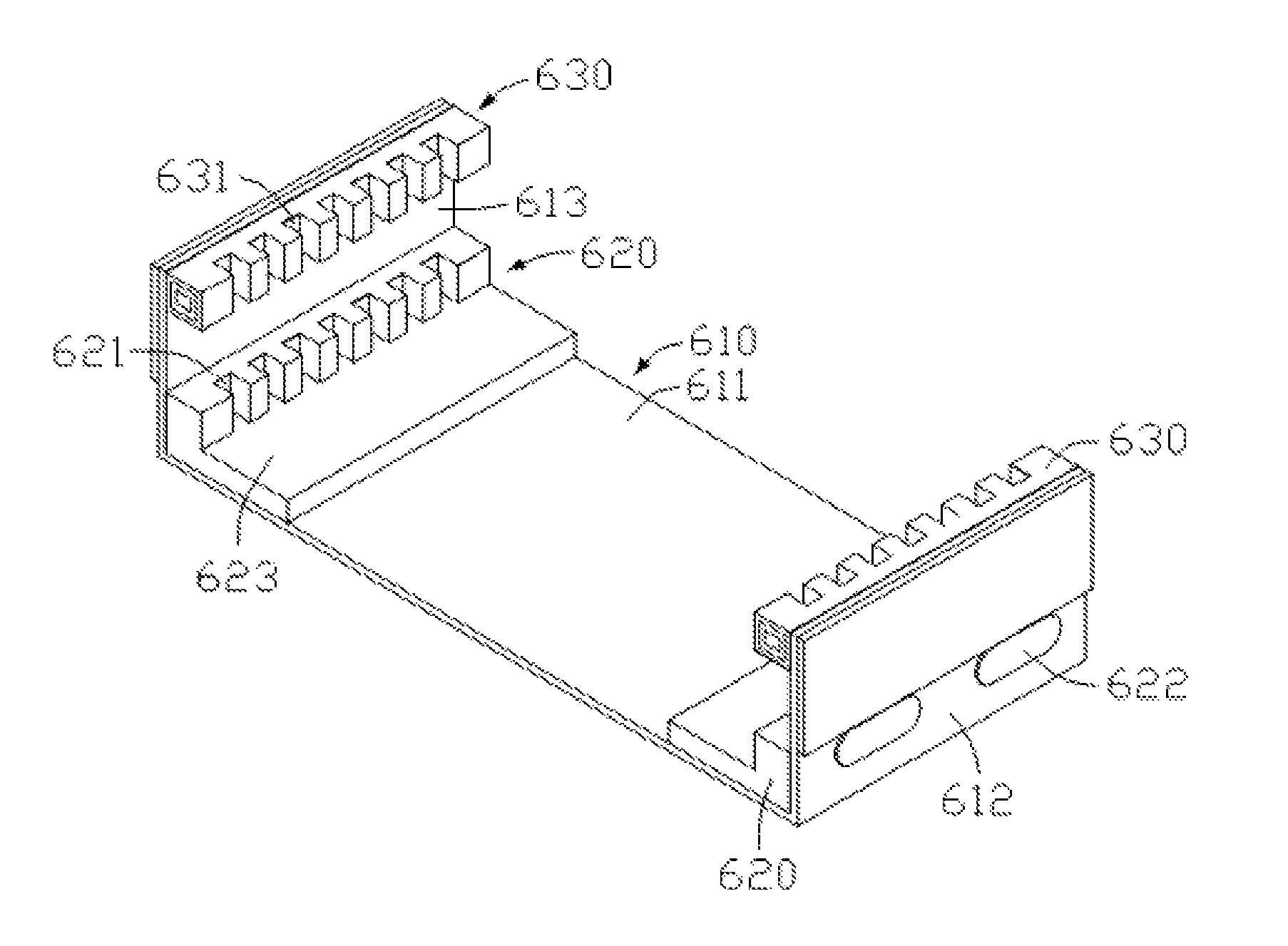
[0039]Referring to FIG. 6, a lower cushioning structure for a display panel according to an embodiment of the present invention comprises:

[0040]a supporting frame 610, comprising a baseplate 611 as well as a first side plate 612 and a second side plate 613 extending upwards from two opposite sides of the baseplate 611;

[0041]two first cushions 620, being disposed at a position where the first side plate 612 of the supporting frame 610 borders the baseplate 611 and a position where the second side plate 613 borders the baseplate 611 respectively;

[0042]two second cushions 630, being disposed on an inner wall of the first side plate 612 and an inner wall of the second side plate 613 respectively, wherein the second cushions 630 are located above the first cushions 620;

[0043]wherein,

[0044]each of the first cushions 620 is formed, on an inner sidewall thereo...


PUM

PropertyMeasurementUnit
thicknessaaaaaaaaaa
heightaaaaaaaaaa
widthaaaaaaaaaa

Abstract

A lower cushioning structure and a package cushioning structure for a display panel are disclosed. The lower cushioning structure comprises: a supporting frame, comprising a baseplate as well as a first side plate and a second side plate extending upwards from two opposite sides of the baseplate respectively; two first cushions, being disposed at a location where the first side plate of the supporting frame borders the baseplate and a location where the second side plate of the supporting frame borders the baseplate respectively; and two second cushions, being disposed on an inner wall of the first side plate and an inner wall of the second side plate of the supporting frame respectively, wherein the second cushions are located above the first cushions. The present invention has a low cost and can provide satisfactory cushioning for the display panel.

Description

TECHNICAL FIELD[0001]The present disclosure generally relates to the field of article packaging technologies, and particularly, to a lower cushioning structure and a package cushioning structure for a display panel.BACKGROUND[0002]Conventionally, during storage, transportation and production of display panels, necessary package cushioning structures must be used for purpose of fixation and protection. Particularly for large-sized display panels such as liquid crystal display (LCD) panels, they are usually arranged in the form of a stack and spaced apart from each other, so cushioning measures must be taken therebetween to prevent damage caused by impact.[0003]Conventional solutions for package cushioning of the display panels are as follows:[0004]Solution I: referring to FIG. 1, a corrugated cardboard 110 is dented, die cut, bonded, interdigitated and assembled, and is then put into a corrugated carton having both a cover and a bottom to cushion the display panels. Although this sol...

Claims


Application Information

Patent Timeline
Patent Type & Authority Patents(United States)
IPC IPC(8): B65D81/02
CPCB65D5/5088B65D5/5085
Inventor HU, QIANSHUANG
Owner TCL CHINA STAR OPTOELECTRONICS TECH CO LTD
Why Eureka
Try Eureka