Shock absorber

A shock absorber, hollow technology, applied in the direction of shock absorbers, shock absorbers, springs/shock absorbers, etc., can solve problems such as noise, reduced quality satisfaction, and reduced durability

Active Publication Date: 2009-06-10
HL MANDO CORP
View PDF0 Cites 23 Cited by
  • Summary
  • Abstract
  • Description
  • Claims
  • Application Information

AI Technical Summary

Problems solved by technology

However, the hollow cavity 20 has a limited size, and thus, the range of motion of the floating piston 22 is limited, thereby providing a lower effect in reducing the damping force.
In addition, when the size of the hollow cavity 20 is increased to improve the effect of reducing the cushioning force, there are problems such as an increase in the manufacturing cost of the piston rod 14 and a decrease in durability.
Additionally, conventional shock absorbers experience friction between the outer surface of the floating piston and the inner surface of the hollow cavity as the floating piston moves up and down within the hollow cavity, causing ineffective initial motion and stickiness between the floating piston and the hollow cavity. Slip (stick slip) phenomenon, thereby reducing driving comfort
In addition, ordinary shock absorbers generate noise when the floating piston contacts the upper or lower end of the upper chamber or the lower chamber, thus reducing quality satisfaction

Method used


Image

  • Shock absorber
  • Shock absorber
  • Shock absorber

Examples


Embodiment Construction

[0027] Exemplary embodiments of the present invention will be described in detail below with reference to the accompanying drawings.

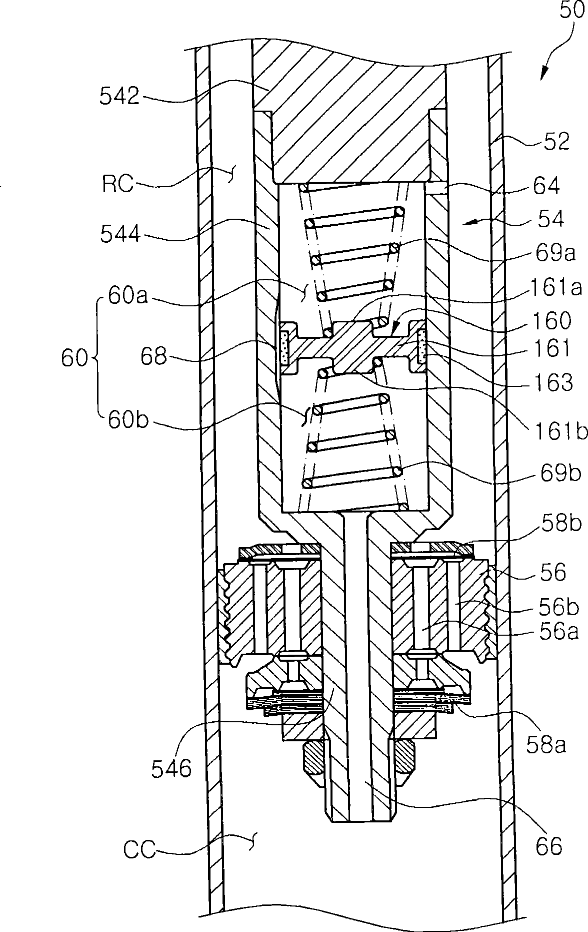
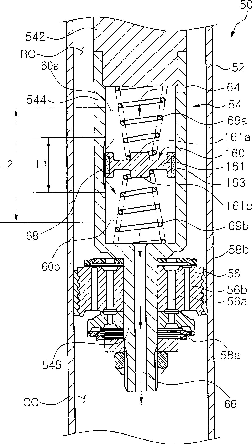
[0028] figure 2 is an enlarged sectional view of a part of the shock absorber according to the first embodiment of the present invention.

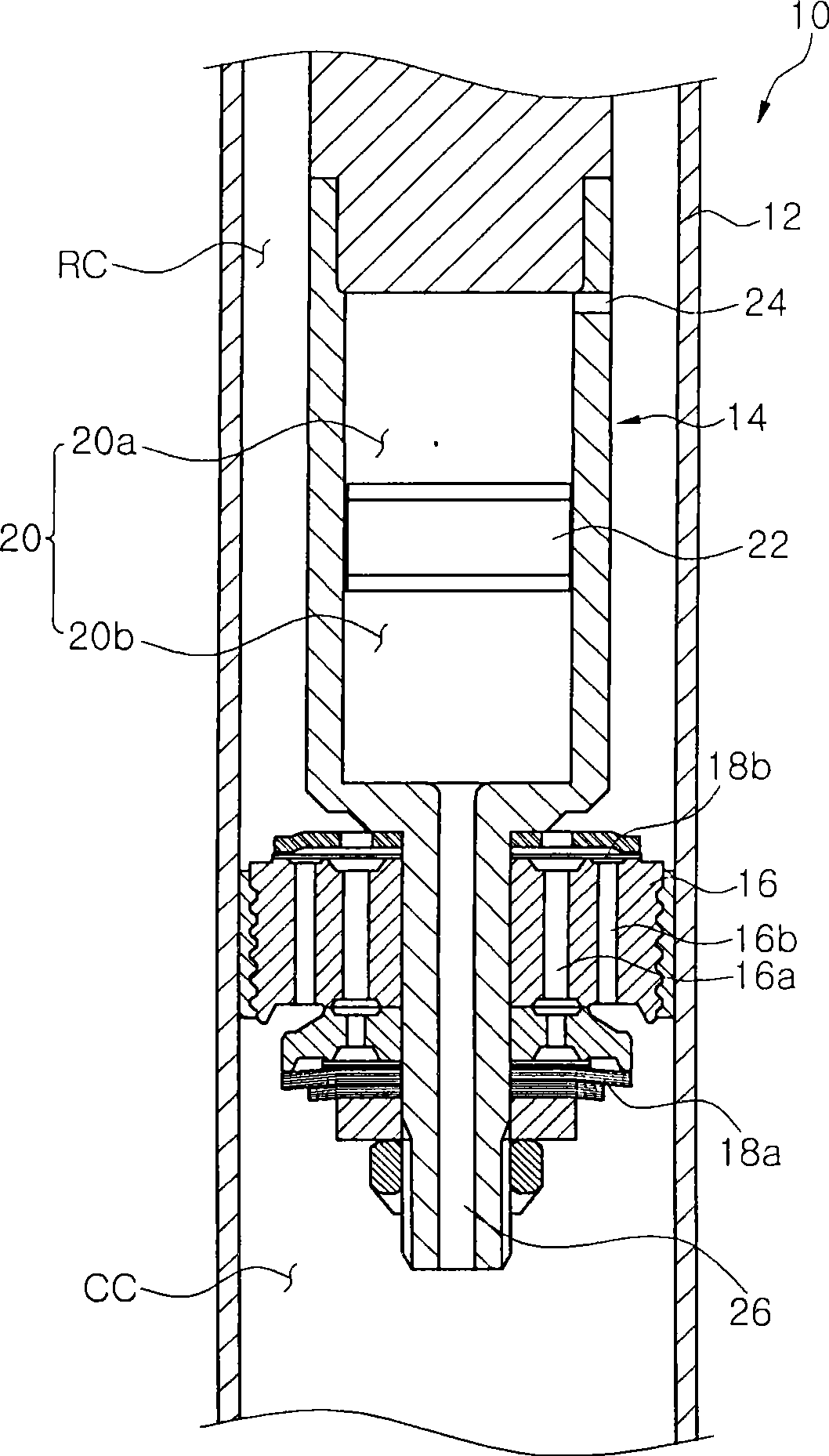
[0029] figure 2 Among them, the shock absorber 50 according to the first embodiment of the present invention includes a cylinder 52 connected to an axle of a vehicle and a piston rod 54 connected to a vehicle body side. A piston rod 54 is disposed within the cylinder 52 to reciprocate therein and includes a piston valve 56 disposed at one end of the piston rod 54 so as to divide the interior of the cylinder 52 into a compression chamber CC and a tensile chamber RC. The piston valve 56 is formed with a stretch hole 56a and a compression hole 56b through which the stretch chamber RC communicates with the compression chamber CC. In addition, a plurality of disk valves 58a and 58b are located on the upper ...


PUM


Abstract

Disclosed herein is a shock absorber for damping vibration transmitted to a vehicle according to a road state. The shock absorber includes a cylinder and a piston valve disposed within the cylinder and connected to a piston rod to divide the cylinder into a first chamber and a second chamber. The piston rod includes a hollow chamber formed within the piston rod, first and second orifices formed in upper and lower ends of the hollow chamber and connected to the first and second chambers, respectively, a floating piston disposed within the hollow chamber to move up and down and to divide the hollow chamber into upper and lower chambers, and a moving mechanism formed in the hollow chamber to move an operating fluid to upper and lower portions of the floating piston. The shock absorber can change a damping force according to a displacement of the piston rod, thereby improving driving comfort and stability of the vehicle.

Description

technical field [0001] The present invention relates to a shock absorber for buffering vibration transmitted to a vehicle according to road conditions, and more particularly, to a shock absorber capable of changing a buffer force according to movement of a piston rod. Background technique [0002] Generally, a vehicle is provided with a suspension system to enhance driving comfort by damping shock or vibration transmitted from a road to an axle during driving. One of the components that make up a suspension system is the shock absorber. The shock absorber is provided between the axle and the body. The shock absorber consists of a cylinder and a piston rod that reciprocates inside the cylinder. The cylinder is filled with working fluid, such as gas or oil, so that the working fluid is moved by a piston valve, which is fixed to one end of the piston rod, to generate a damping force. [0003] Ordinary shock absorbers have the limitation of having constant damping force chara...

Claims


Application Information

Patent Timeline
Patent Type & Authority Applications(China)
IPC IPC(8): F16F9/19F16F9/32
CPCF16F9/3214F16F9/3221F16F9/34F16F9/5126F16F9/54
Inventor 金南昊
Owner HL MANDO CORP
Why Eureka
Try Eureka