Power supply circuit and control method of the same

a power supply circuit and control method technology, applied in the direction of power supply for data processing, process and machine control, instruments, etc., can solve the problems of increasing the dielectric strength of parts, not economical, and the operation of mobile devices stops, so as to prevent an abrupt change in voltage output, stable rise of power supply, and effective reduction of power consumption

Active Publication Date: 2009-12-17
RENESAS ELECTRONICS CORP
View PDF22 Cites 11 Cited by
  • Summary
  • Abstract
  • Description
  • Claims
  • Application Information

AI Technical Summary

Benefits of technology

[0017]A first exemplary aspect of an embodiment of the present invention is a power supply circuit that includes a first boosting circuit to boost a power supply voltage supplied from a power supply and generate a first boosted voltage, a second boosting circuit to boost the power supply voltage at a higher multiplication factor than the first boosting circuit and generate a second boosted voltage, a switching circuit to output one of the first boosted voltage and the second boosted voltage, a first capacitor placed at an output end of the switching circuit, and a second capacitor placed at an output end of the second boosting circuit. In this configuration, when switching from the first boosted voltage to the second boosted voltage, it is possible to use, not abandon, charge charged in the first capacitor, thereby effectively reducing power consumption. Further, it is possible to prevent an abrupt change in the voltage output from the power supply circuit upon switching, thereby allowing stable rise in power supply.
[0018]A second exemplary aspect of an embodiment of the present invention is a control method of a power supply circuit including a first boosting circuit to boost a power supply voltage supplied from a power supply and generate a first boosted voltage and a second boosting circuit to boost the power supply voltage at a higher multiplication factor than the first boosting circuit and generate a second boosted voltage. The control method includes smoothing the first boosted voltage by a first capacitor when the power supply voltage is equal to or higher than a prescribed value, and smoothing the second boosted voltage by a second capacitor and the first capacitor when the power supply voltage is lower than the prescribed value. In this method, when switching from the first boosted voltage to the second boosted voltage, it is possible to use, not abandon, charge charged in the first capacitor, thereby effectively reducing power consumption. Further, it is possible to prevent an abrupt change in the voltage output from the power supply circuit upon switching, thereby allowing stable rise in power supply.
[0019]According to the exemplary aspects of an embodiment of the present invention described above, it is possible to provide a power supply circuit capable of preventing malfunction of apparatus and elongating battery life, and a control method of the same.

Problems solved by technology

When the output voltage of the boosting circuit falls below a prescribed voltage value that is necessary for driving the mobile apparatus, the mobile apparatus stops operating, considering that the battery life runs out.
However, if the voltage is boosted with a large multiplication factor from the beginning, it is necessary to increase the dielectric strength of parts to which the boosted voltage is supplied, which is not economical.
However, the present inventor has found that the following problem occurs when switching between a plurality of boosting circuits with different output voltages by the power supply selection circuit in the power supply circuit according to prior art.
When switching the output of the boosting circuit by the power supply selection circuit, the charge charged in the smoothing capacitor is abandoned, which is significant waste of power.
Further, when switching from a boosting circuit that generates a low boosted voltage to a boosting circuit that generates a high boosted voltage, the power supply voltage rises abruptly at the output of the power supply selection circuit, which may cause an adverse effect on loads.
An abrupt change in the power supply voltage of the entire circuit may cause malfunction such as an abrupt flow of current into a part of the circuit.

Method used


Image

  • Power supply circuit and control method of the same
  • Power supply circuit and control method of the same
  • Power supply circuit and control method of the same

Examples


Embodiment Construction

[0028]An exemplary embodiment of the present invention will be described hereinbelow. The explanation provided hereinbelow merely illustrates an exemplary embodiment of the present invention, and the present invention is not limited to the below-described exemplary embodiment. The following description and the accompanying drawings are appropriately shortened and simplified to clarify the explanation. Further, redundant explanation is omitted as appropriate to clarify the explanation. In the figures, the identical reference symbols denote identical elements and the explanation thereof is omitted as appropriate.

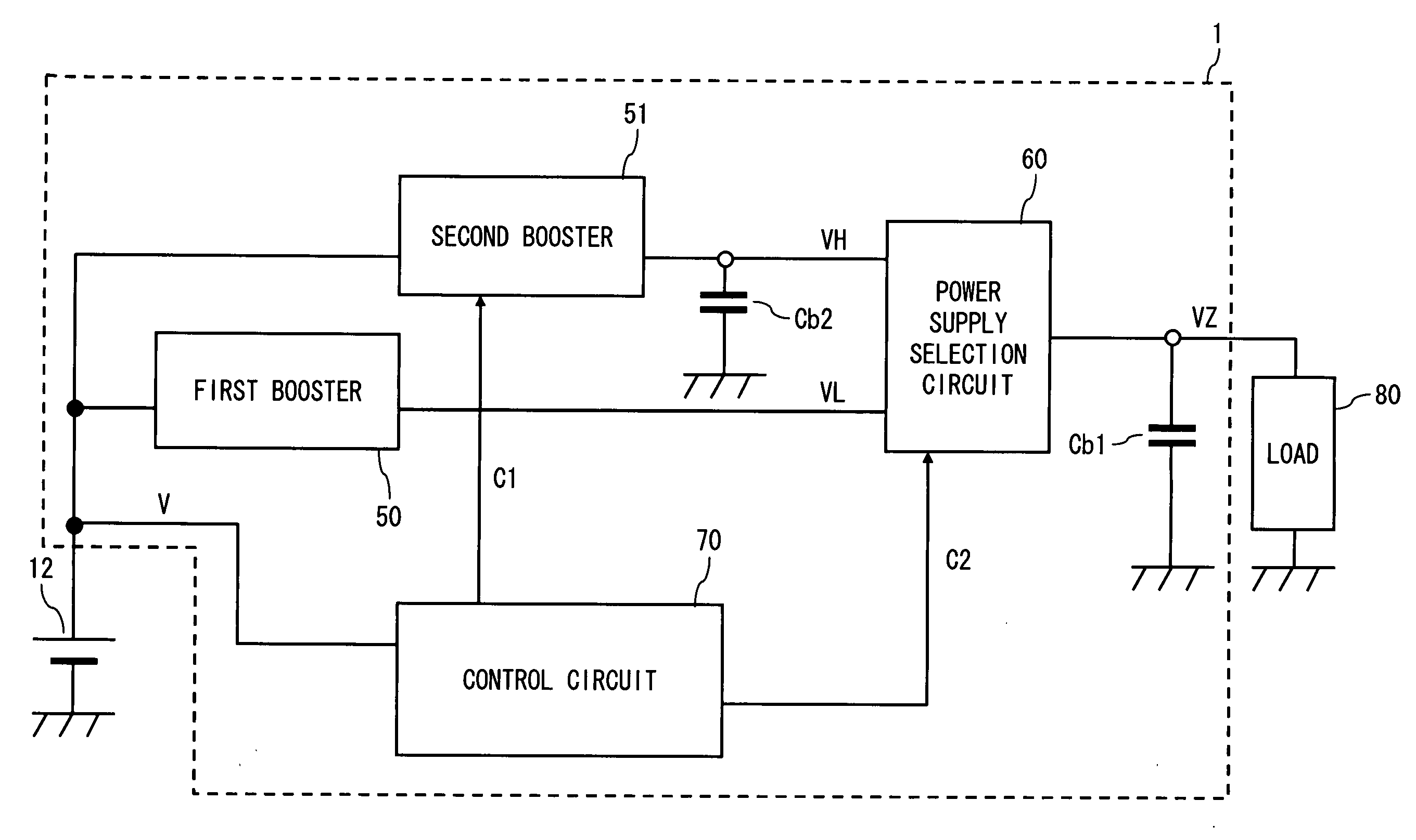
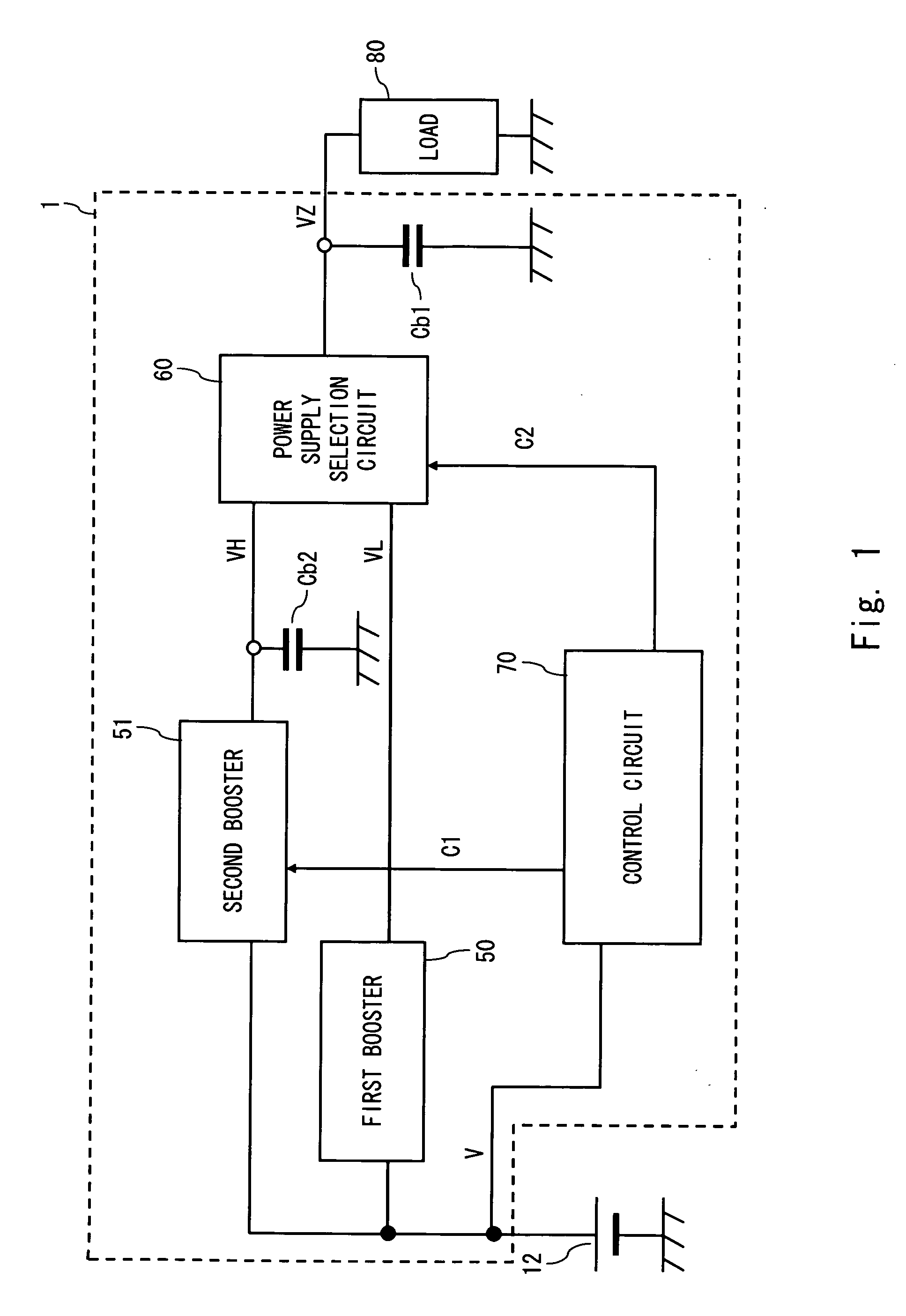
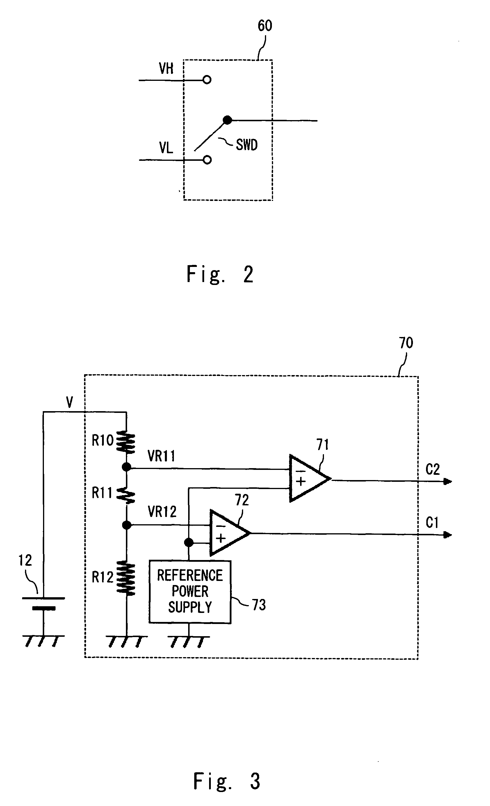
[0029]The configuration of a power supply circuit according to an exemplary embodiment of the present invention is described hereinafter with reference to FIG. 1. FIG. 1 is a block diagram showing the configuration of a power supply circuit according to the exemplary embodiment. A power supply circuit 1 according to the exemplary embodiment controls supply of a voltage for dri...


PUM


Abstract

A power supply circuit is provided which includes a first booster to boost a power supply voltage supplied from a battery and generate a first boosted voltage, a second booster to boost the power supply voltage at a higher multiplication factor than the first booster and generate a second boosted voltage, a power supply selection circuit to output the first boosted voltage or the second boosted voltage, a first smoothing capacitor placed at an output end of the power supply selection circuit, and a second smoothing capacitor placed at an output end of the second booster.

Description

BACKGROUND[0001]1. Field of the Invention[0002]The present invention relates to a power supply circuit and a control method of the same and, particularly, to a power supply circuit using a battery as a power supply and a control method of the same.[0003]2. Description of Related Art[0004]In mobile apparatus, a variety of devices such as a display device are driven using a power supply voltage that is supplied from an internal battery. Battery life is one of the most important considerations when a user chooses a mobile apparatus. Thus, a mobile apparatus with long battery life is advantageous in terms of apparatus choice. Recently, various developments have been made to elongate the battery life of mobile apparatus.[0005]Although only one power supply voltage is supplied from a battery, a mobile apparatus incorporating a display device generally requires a plurality of voltages including a voltage higher than the power supply voltage of the battery in order to drive the display devi...

Claims


Application Information

Patent Timeline
Patent Type & Authority Applications(United States)
IPC IPC(8): G05F3/16
CPCG06F1/26G09G2330/02G09G3/3611
Inventor HISANO, HARUHIKO
Owner RENESAS ELECTRONICS CORP
Why Eureka
Try Eureka