Image encoding apparatus, method of controlling the same and computer program

a technology of image encoding and control apparatus, applied in the field of image encoding technique, can solve the problems of inability to achieve high-speed encoding, low activation rate of circuits that perform each processing step,

Inactive Publication Date: 2009-12-17
CANON KK
View PDF7 Cites 76 Cited by
  • Summary
  • Abstract
  • Description
  • Claims
  • Application Information

AI Technical Summary

Problems solved by technology

In other words, in order to start processing of 4×4 prediction 1302 for a block n+1, it is necessary to wait for the completion of processing up to and including inverse integer transformation 1301 for a block n. As a result, even when pipeline processing is performed, the activation rate of a circuit that performs each processing step is extremely low as shown in FIG. 13, and high-speed encoding cannot be expected.
However, since t...

Method used


Image

  • Image encoding apparatus, method of controlling the same and computer program
  • Image encoding apparatus, method of controlling the same and computer program
  • Image encoding apparatus, method of controlling the same and computer program

Examples


first embodiment

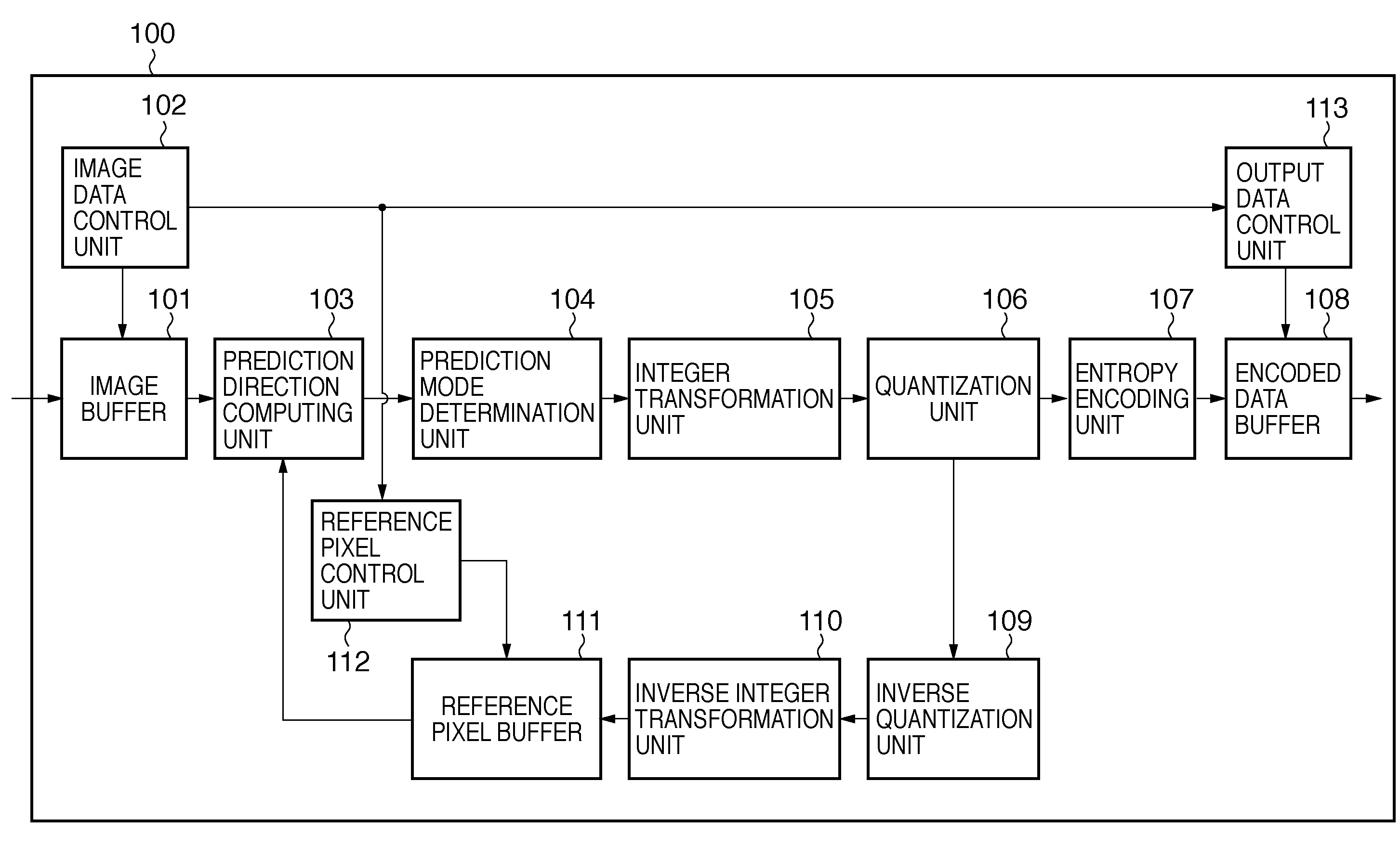
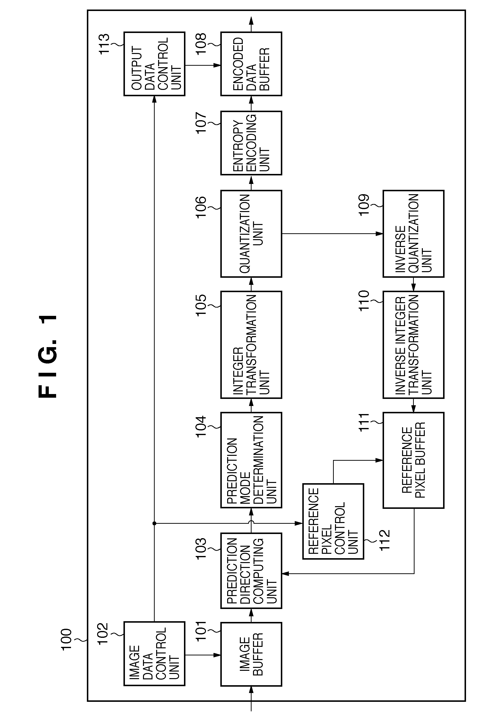
[0029]FIG. 1 is an example of a functional block diagram of an image encoding apparatus 100 according to a first embodiment of the present invention. All of the components may be implemented by hardware, or some of the components may be implemented by software. Input image data from an external camera or the like (not shown) is written to the image encoding apparatus 100 in units of macroblocks of 16×16 pixels. The macroblocks of the input image data are held in an image buffer 101.

[0030]An image data control unit 102 partitions each macroblock into blocks of 4×4 pixels each. A “block” as simply expressed hereinbelow means a block of 4×4 pixels. The image data control unit 102 then reads out a block to be processed from the image buffer 101. A prediction direction computing unit 103 calculates a difference value between a reference pixel and a pixel of the block to be encoded for each of a plurality of prediction directions. A prediction mode determination unit 104 selects the diffe...

second embodiment

[0060]In the first embodiment, the efficiency of pipeline processing was improved by performing encoding processes in the order in which the first block for which all of the prerequisite reference pixels are available is the first to be processed. However, when entropy encoding and the like 807 takes a long processing time, in some cases, a sufficient effect cannot be obtained with the configuration of the first embodiment. An example of such a case will be described using FIG. 8.

[0061]FIG. 8 is a diagram for explaining an example of a time chart of pipeline processing in the case where entropy encoding and the like 807 takes a long processing time. In the description here, encoding processes of B2 and B4 will be focused on. At a stage when 4×4 prediction 701 for B2 is completed, 4×4 prediction 701 for B4 can be started. However, entropy encoding and the like 807 for B4 cannot be started until processing of entropy encoding and the like 807 for B2 is completed. Thus, even when proce...


PUM


Abstract

An image encoding apparatus that performs intra-frame predictive encoding is provided. The apparatus includes a partitioning unit configured to partition an inputted macroblock into blocks as processing units, an encoding unit configured to encode each of blocks to be processed using a prediction value for each pixel contained in the block to be processed, the prediction value being calculated by referring to pixels contained in other blocks, and a sorting unit configured to sort the encoded blocks in a predetermined encoding order. The encoding unit starts encoding in an order in which the first block for which all the pixels to be referred to are available for calculation of the prediction value is the first to be encoded, and the encoding is performed by pipeline processing.

Description

BACKGROUND OF THE INVENTION[0001]1. Field of the Invention[0002]The present invention relates to an image encoding technique, and particularly relates to an image encoding technique with respect to an intra-frame predictive encoding process.[0003]2. Description of the Related Art[0004]MPEG-4 and H.264 are known as image encoding systems adopting an encoding method that performs intra-frame prediction. Intra-frame prediction in H.264 is an evolution of intra-frame prediction in MPEG-4 and can enhance encoding efficiency. The main differences in intra-frame predictive encoding between MPEG-4 and H.264 are that the number of data items to be predicted is increased, the number of blocks to be referred to is increased, the direction of prediction is encoded, the number of types of blocks to be predicted is increased, and so on.[0005]Hereinafter, intra-frame predictive encoding for blocks of 4×4 pixels each in H.264 will be described using FIGS. 10 to 13. FIG. 10 is a diagram showing pred...

Claims


Application Information

Patent Timeline
IPC IPC(8): H04N7/26H03M7/36G06K9/36H04N19/12H04N19/134H04N19/136H04N19/423H04N19/436H04N19/50H04N19/593H04N19/60H04N19/61H04N19/91
CPCH04N19/593H04N19/42H04N19/11
Inventor TANAKA, EIICHI
Owner CANON KK
Why Eureka
Try Eureka