Image forming device and image forming method
- Summary
- Abstract
- Description
- Claims
- Application Information
AI Technical Summary
Benefits of technology
Problems solved by technology
Method used
Image

Examples
embodiment 1
[0045]First, a description is made on an image forming device 1 in accordance with Embodiment 1 of the present invention.
(1. Structure)
(1-1. Basic Structure)
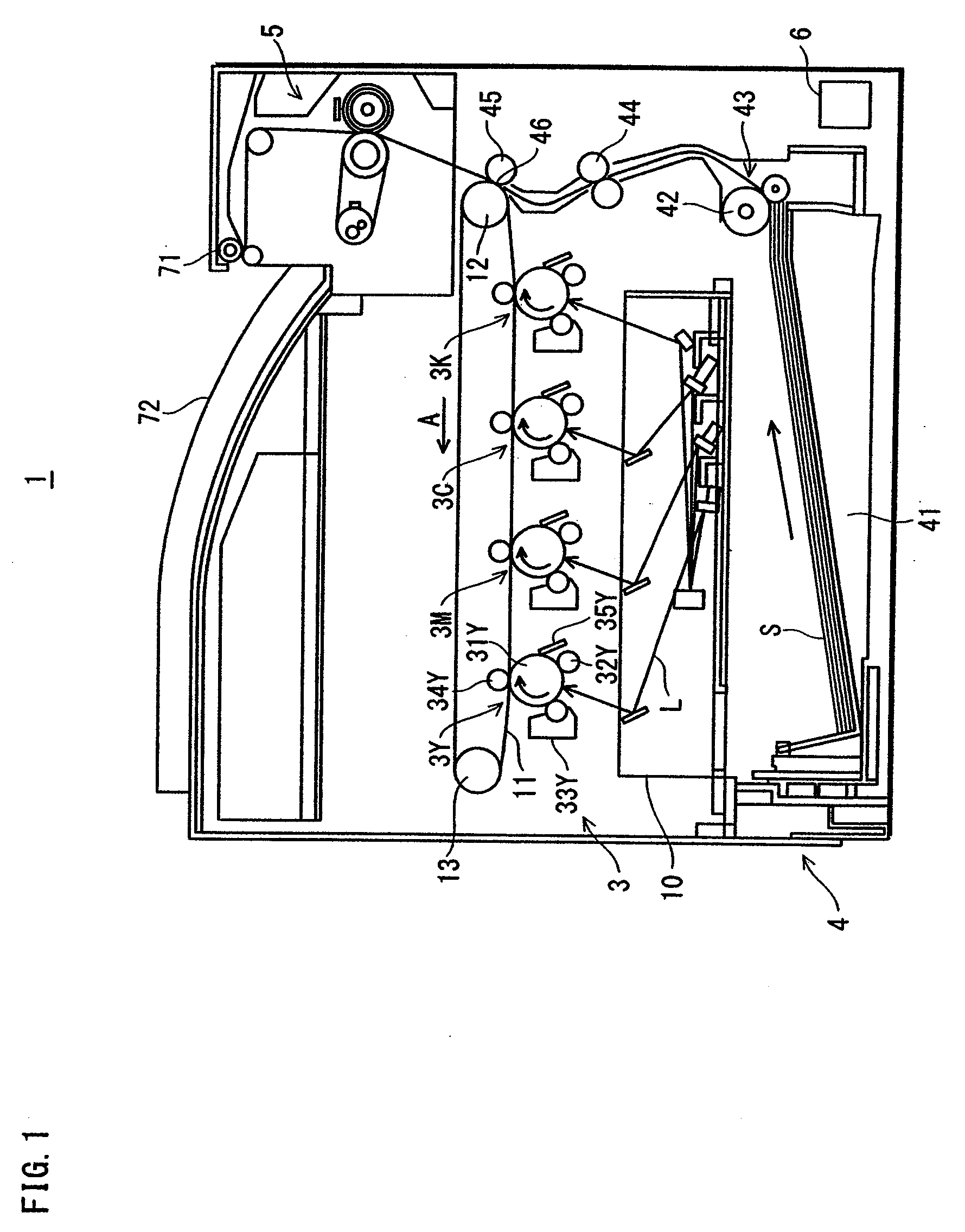
[0046]With the reference to FIG. 1, a description is made on an outline structure of an image forming device 1 which is a tandem-type color printer.
[0047]As shown in FIG. 1, the image forming device 1 includes an image processor 3, a feeder 4, a fixer 5, and a controller 6. The image forming device 1 is connected to a network (e.g. LAN), and upon receiving an image forming execution instruction from an unillustrated external terminal apparatus, executes color image formation in accordance with the instruction, the color image being composed of colors yellow, magenta, cyan, and black. The yellow, magenta, cyan and black reproduction colors are hereinafter represented as Y, M, C, and K respectively, and the letters Y, M, C, and K have been appended to numbers of elements pertaining to the reproduction colors.
[0048]The image proces...
embodiment 2
[0116]Subsequently, a description is made on an image forming device 2 in accordance with Embodiment 2.
[0117]Embodiment 1 shows an example in which the CPU 61 control the temperature, in two steps, to be kept at substantially at two intermediate temperatures when the low-temperature fixing state is switched to the standby temperature state, whereas Embodiment 2 shows an example in which the CPU 61 controls the temperature to be kept substantially at one intermediate temperature.
[0118]The following describes the image forming device 2, focusing differences from the image forming device 1 of Embodiment 1.
(1. Difference in Structure)
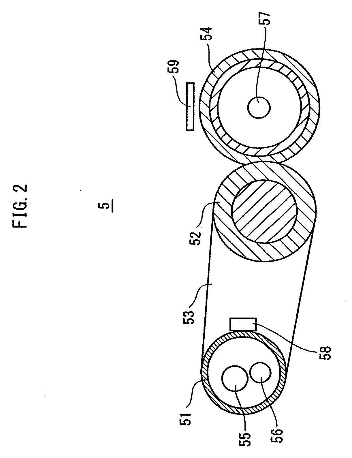
[0119]When an image is fixed at a low temperature, the temperature control program 64b obtains one intermediate temperature by calculating a temperature being intermediate between the fixing temperature and the standby temperature. The temperature control program 64b controls the temperature of the heating roller 51 to be kept substantially at the intermedi...
embodiment 3
[0128]Subsequently, a description is made on an image forming device 3 in accordance with Embodiment 3.
[0129]Embodiment 2 shows an example in which the CPU 61 controls the temperature to be kept substantially at the intermediate temperature, with the heating roller 51 kept rotating when the low-temperature fixing state is switched to the standby temperature state. Embodiment 3 shows an example in which the CPU 61 controls the temperature to be kept substantially at the intermediate temperature, with the heating roller 51 being stopped.
[0130]The following describes the image forming device 3, focusing differences from the image forming device 2 of Embodiment 2.
(1. Difference in Operation)
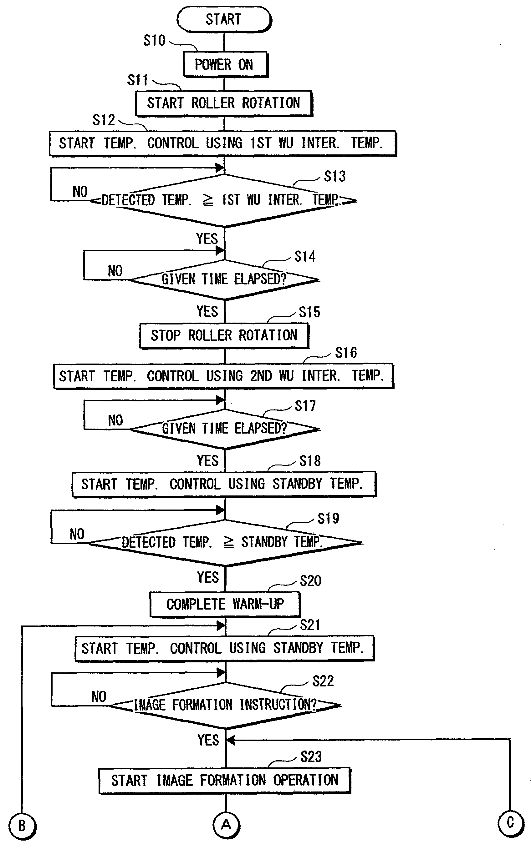
[0131]Since the warm-up operation of the image forming device 3 is basically identical with that of the image forming device 2, a detailed description thereof is omitted here. With the reference to the flowchart in FIG. 9, a description is made on the operation of the image forming device 3 during an...
PUM
 Abstract
Description
Claims
Application Information
 - R&D
- Intellectual Property
- Life Sciences
- Materials
- Tech Scout
- Unparalleled Data Quality
- Higher Quality Content
- 60% Fewer Hallucinations
Browse by: Latest US Patents, China's latest patents, Technical Efficacy Thesaurus, Application Domain, Technology Topic, Popular Technical Reports.
© 2025 PatSnap. All rights reserved.Legal|Privacy policy|Modern Slavery Act Transparency Statement|Sitemap|About US| Contact US: help@patsnap.com