Electrical connector and inserting method thereof

a technology of electrical connectors and connectors, applied in the direction of electrical discharge lamps, coupling device connections, electric discharge tubes, etc., can solve the problems of system and memory card damage, etc., and achieve the effect of stably transmitting signals

Inactive Publication Date: 2009-12-17
LOTES
View PDF9 Cites 13 Cited by
  • Summary
  • Abstract
  • Description
  • Claims
  • Application Information

AI Technical Summary

Benefits of technology

[0016]Comparing with conventional electrical connectors, the electrical connector of the present invention includes the main body portion which has the receiving space concavely formed in the front end thereof and the plurality of spaced first conductive terminals disposed on the top surface of the receiving space. When a plug assembly (for example, memory card, Micard) is inserted into the electrical connector, the surface of the memory card with contacting points is electrically connected with the first conductive terminals located in the receiving space and the surface of the memory card without contacting points attaches to the bottom surface of the receiving space, so that the memory card is only electrically connected with the first conductive terminals, so there is no other in-series disturbed signal noise for stable signal transmission. Furthermore, the main body portion has the protrusion extending forwards from the front end thereof, and the protrusion has the guiding surface formed on a top thereof and connected with the bottom surface of the receiving space, so the memory card enters the receiving space from the guiding surface when being inserted, that is, the memory card can be received in the longer inserting space which is formed by the space above the guiding surface and the receiving space, so the protruding portion of the memory card, which extends out of the electrical connector when the memory card is inserted in its position, is short, thereby the memory card cannot swing and can be connected stably. Additionally, the plurality of spaced second conductive terminals is disposed on the guiding surface of the protrusion, and when each second conductive terminal is extended to the cutout, the second conductive terminal is bent and extends downward to form the second connecting portion. The second conductive terminal doesn't like each first conductive terminal which is bent and extends downward after extending rearwards through the rear end of the main body portion. So the whole length of each second conductive terminal is reduced, so that manufacturing materials are saved, production cost is reduced, and signal transmission distance effectively decreases and the resistance is reduced, which is favorable to high-frequency transmission.

Problems solved by technology

However, because the memory card 4 is too long and the protruding portion of the memory card 4 which extends out of the connector 100 is too long, so the memory card 4 is easy to swing and touch other objects so that the memory card 4 and the USB connector 100 are damaged.
So there firstly occurs short conduction, then short non-conduction, and finally stable electrical connection between the memory card 4 and the electrical connector during the inserting of the memory card 4, which is easy to cause that the system and the memory card are damaged.
However, because the interfaces of the memory card 4 operate at different voltages and transmit different signals after being electrically connected, the contact of the front contacting portion 123 of the conductive terminal 120 and contacting points of other interfaces on the surface of the memory card 4 will cause that non-specific conduction occurs and signals are transmitted in disorder, thereby damaging the system and the memory card.

Method used


Image

  • Electrical connector and inserting method thereof
  • Electrical connector and inserting method thereof
  • Electrical connector and inserting method thereof

Examples


Embodiment Construction

[0031]To further understand features and technical contents of the present invention, please refer to the drawings and the following detailed description related the electrical connector according to the present invention.

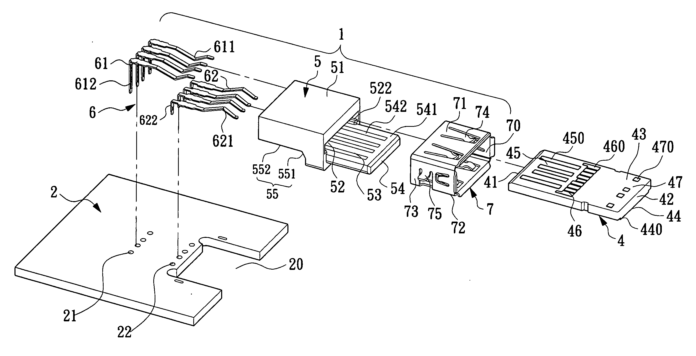
[0032]Please refer to FIG. 5, FIG. 7 and FIG. 12, an electrical connector 1 of the present invention may be mounted on a circuit board 2 for being connected with a socket assembly (for example, a standard USB socket connector) 3 or a plug assembly (for example, memory card, Micard) 4. The electrical connector 1 includes an insulating body 5, a plurality of conductive terminals 6 and a shielding casing 7.

[0033]Please refer to FIGS. 5-8, the insulating body 5 includes a main body portion 51. A first receiving space (inserting space) 52 is concavely formed in the main body portion 51 and extends from a front end face of the main body to a rear end face of the main body. A plurality of spaced first terminal passages 521 extends between a top of the main body portion 51...


PUM


Abstract

An electrical connector includes an insulating body with a main body portion in which a first receiving space is concavely formed. Spaced first terminal passages extend in a top surface of the first receiving space. A second receiving space is formed in the front end of the main body portion and connected with the first receiving space. A tongue plate extends forwards from a front end face of the main body portion and has a working surface in which spaced second terminal passages extend. The second receiving space is located above the tongue plate. First and second conductive terminals are respectively correspondingly received in the first and the second terminal passages. When a memory card is inserted into the connector, there is no other in-series disturbed signal noise for stable signal transmission; and when the memory card is inserted to its position, it cannot swing and can be connected stably.

Description

BACKGROUND OF THE INVENTION[0001]1. Field of the Invention[0002]The present invention relates to an electrical connector, and more especially to an electrical connector which can be not only connected with a socket assembly (for example, a standard USB socket connector), but also securely connected with a plug assembly (for example, a memory card), and method of inserting the electrical connector.[0003]2. Description of Related Art[0004]Universal Serial Bus (USB) is an electrical connector which can transmit high-speed signals. At present, USB is widely used to connect all kinds of electronic hosts and external devices. With the popularity of USB connectors, various electrical connectors are designed to have expansion functions and simultaneously transmit standard USB interface electrical signals and other additional electrical signals (for example, memory card electrical signals) based on original USB standard.[0005]A standard USB connector 100 (please refer to FIG. 1 and FIG. 2) g...

Claims


Application Information

Patent Timeline
Patent Type & Authority Applications(United States)
IPC IPC(8): H01R27/00
CPCH01R12/725H01R12/721
Inventor CHEN, YU SHENG
Owner LOTES
Why Eureka
Try Eureka