
Collision determination apparatus for vehicle

a technology for determining apparatus and collision, which is applied in the direction of vehicular safety arrangements, pedestrian/occupant safety arrangements, instruments, etc., can solve problems such as ineffective proposals, and achieve the effects of preventing malfunction of collision determination apparatus, ensuring redundancy, and low cos

Active Publication Date: 2009-12-17
DENSO CORP +1
View PDF9 Cites 45 Cited by
  • Summary
  • Abstract
  • Description
  • Claims
  • Application Information

AI Technical Summary

Benefits of technology

The present invention provides a collision determination apparatus for a vehicle at a low cost that can detect collisions with high accuracy regardless of the location of the collision. The apparatus includes a chamber member, a main sensor, a safing sensor, a vehicle speed sensor, and a collision determination unit. The safing sensor senses the pressure of the chamber space as the main sensor, which ensures redundancy in detecting collisions. The apparatus can detect if the vehicle is making a stop or if there is a failure in the main sensor or safing sensor, and prevent malfunctions in the apparatus. The apparatus is effective in ensuring safety and can be provided at a low cost.

Problems solved by technology

However, it is found that there exists no effective proposal on it.

Method used


Image

  • Collision determination apparatus for vehicle
  • Collision determination apparatus for vehicle
  • Collision determination apparatus for vehicle

Examples


Embodiment Construction

[0027]Exemplary embodiments are described below with reference to the accompany drawings.

[0028]There will be described a passenger protection system 100 and a pedestrian protection system 200 in accordance with comparison examples.

[0029]FIG. 9 is a block diagram illustrating operation logic of a passenger protection system 100 according to one comparison example. As shown in FIG. 9, the passenger protection system 100 includes a main sensor 102, a safing sensor 104, an AND circuit 106 and a passenger protection apparatus 108. The main sensor 102 functions as a collision detection sensor for mainly detecting the occurrence of a collision, and is, for example, an acceleration sensor or a pressure sensor. The safing sensor 104 is used for detecting a collision whose direction is the same as that is to be defected by the main sensors 103, and thereby providing redundancy to the passenger protection system 100. The AND circuit 106 performs a logical AND operation between a value associat...


PUM


Abstract

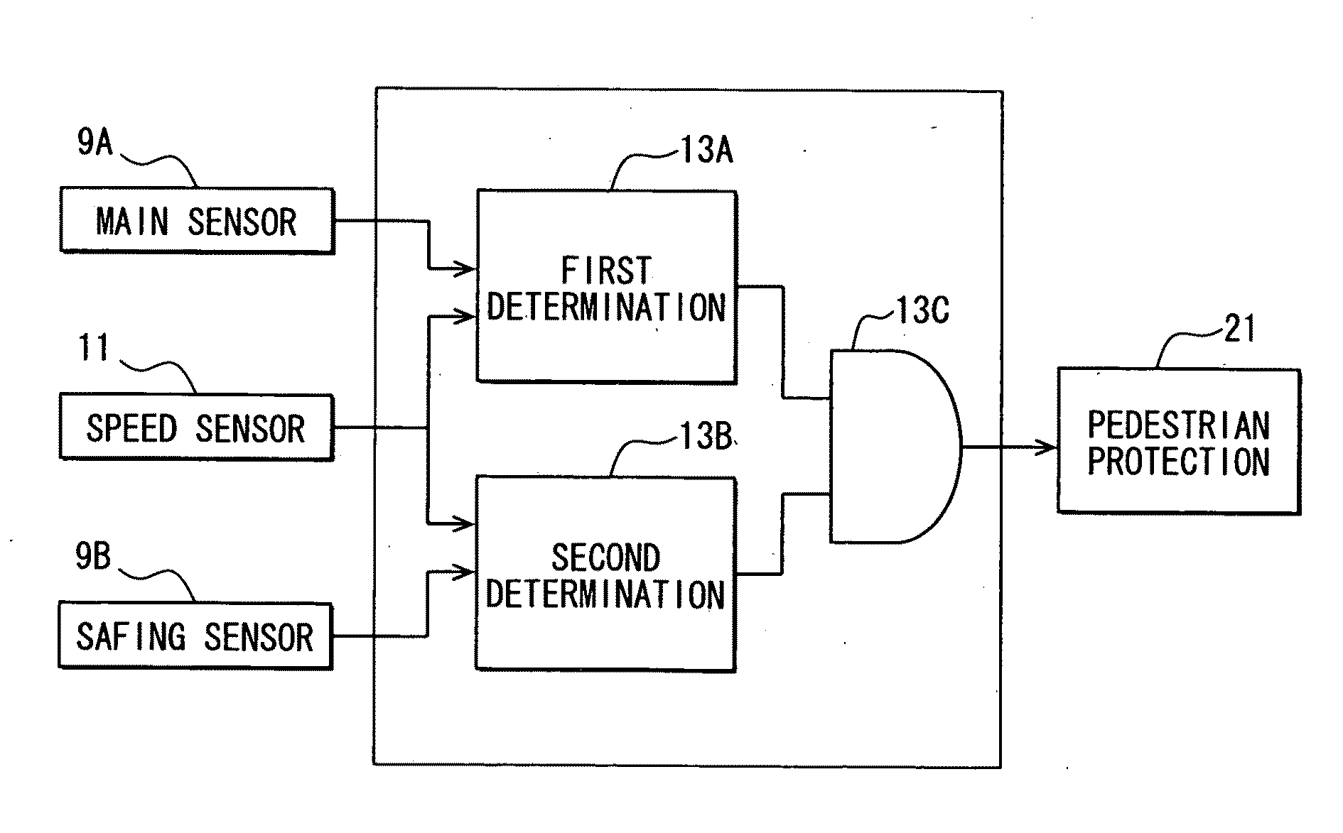
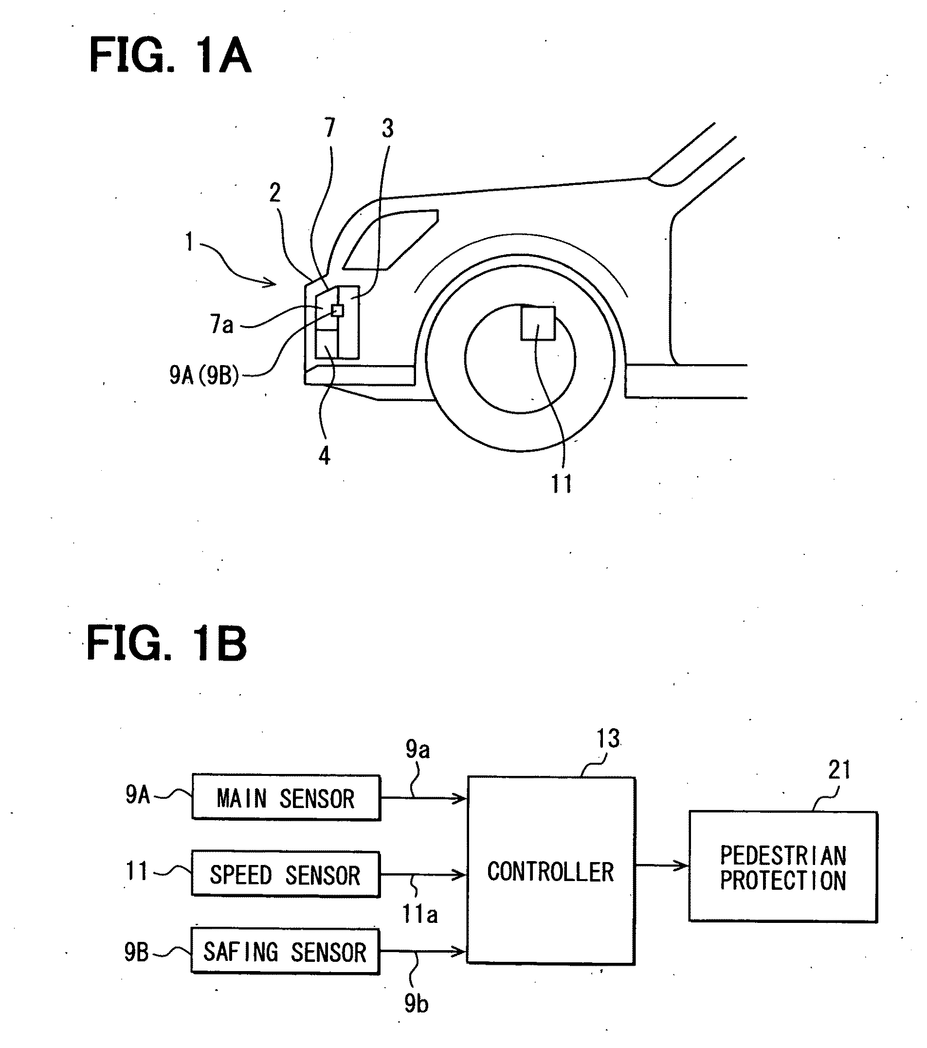
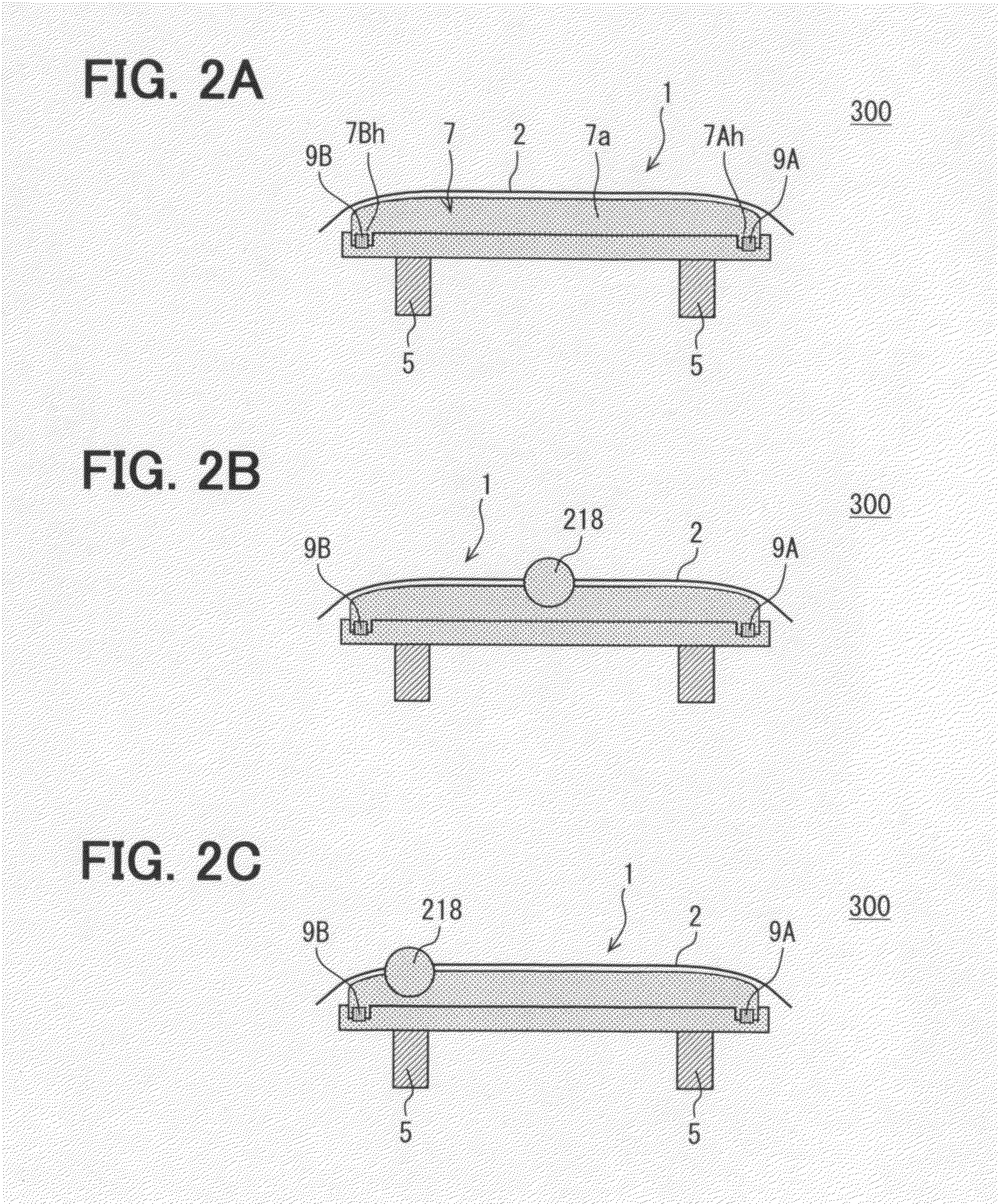
A collision determination apparatus for a vehicle is disclosed. The collision determination apparatus includes: a chamber member that is arranged in a bumper and has therein a chamber space; a main sensor that senses pressure of the chamber space; a safing sensor that senses the pressure of the chamber space independently of the main sensor; and a vehicle speed sensor that senses a speed of the vehicle. The collision determination apparatus detects an occurrence of a collision between an object and a bumper and determines whether the collision necessitates activation of the protection apparatus based on sensing results of the main sensor, the safing sensor and the vehicle speed sensor.

Description

CROSS REFERENCE TO RELATED APPLICATION[0001]The present application is based on Japanese Patent Application No. 2008-154079 filed on Jun. 12, 2008, the disclosure of which is incorporated herein by reference.BACKGROUND OF THE INVENTION[0002]1. Field of the Invention[0003]The present invention relates to a collision determination apparatus for a vehicle, more particularly relates to a vehicle collision determination apparatus that determines an occurrence of a collision based on a pressure change in a bumper of the vehicle.[0004]2. Description of Related Art[0005]Passenger protection systems for a vehicle have been put to practical use. A typical passenger protection system detects a collision between a vehicle and an object, and activates a passenger protection apparatus such as an airbag and the like to protect a passenger of the vehicle. JP-2007-126014A corresponding to US Patent Application Publication No. 2007 / 0106474 proposes a technique for minimizing malfunction of the passen...

Claims


Application Information

Patent Timeline
Patent Type & Authority Applications(United States)
IPC IPC(8): G08G1/16
CPCB60R2021/01027B60R21/0136
Inventor SUZUKITAKAHASHI, HIROYUKI
Owner DENSO CORP
Learn More