Protective Cover With Power Supply Unit For Portable Electronic Device

a technology for protecting covers and electronic devices, applied in rigid containers, instruments, transportation and packaging, etc., can solve the problems of power supply, spare batteries not only occupying additional space in the knapsack, and users are obviously inconvenient to do

Inactive Publication Date: 2009-12-24
LIU KENG YUAN
View PDF4 Cites 205 Cited by
  • Summary
  • Abstract
  • Description
  • Claims
  • Application Information

AI Technical Summary

Benefits of technology

The purpose of this invention is to create a protective covering for an electronics device that has its own battery to keep it running properly. This way, if someone drops their phone or takes it out of use for some time, they can always have access to it without having to charge it first.

Problems solved by technology

The technical problem addressed in this patent text is how to provide both protection and power supply for portable electronics devices without having to remove them from their current protective covers.

Method used


Image

  • Protective Cover With Power Supply Unit For Portable Electronic Device
  • Protective Cover With Power Supply Unit For Portable Electronic Device
  • Protective Cover With Power Supply Unit For Portable Electronic Device

Examples


Embodiment Construction

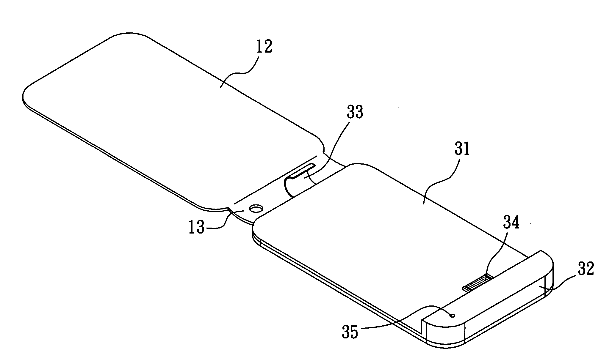
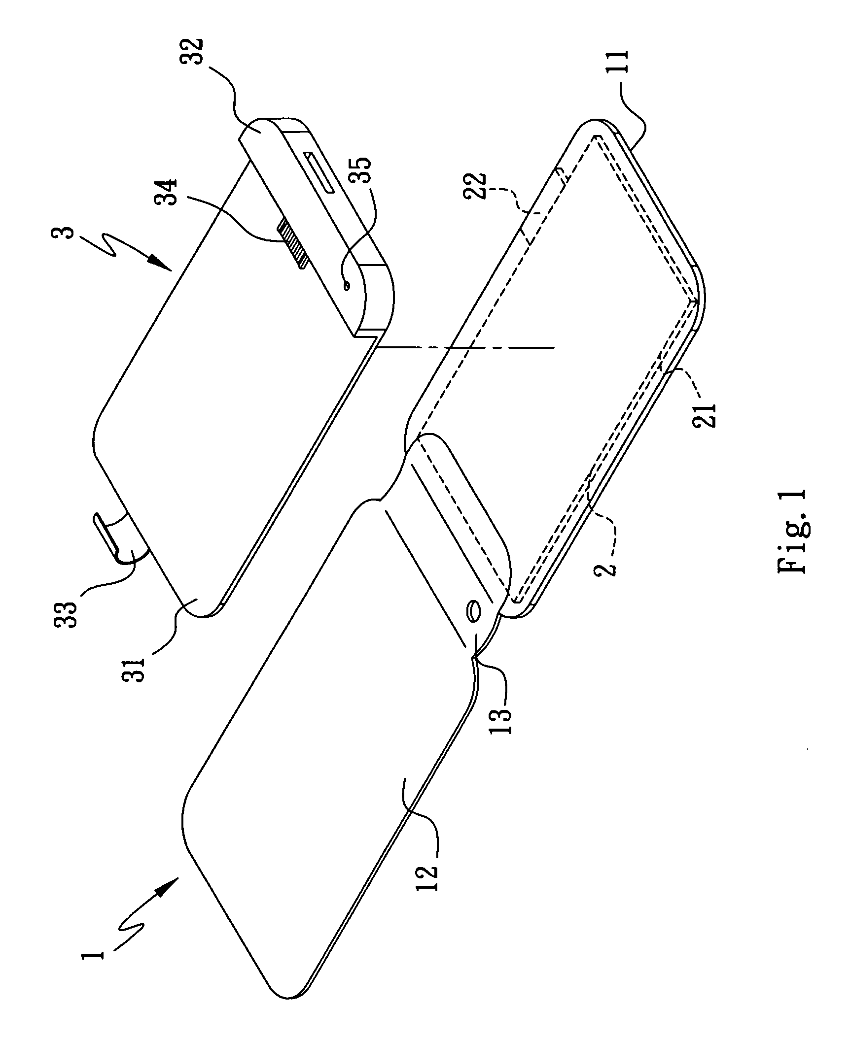
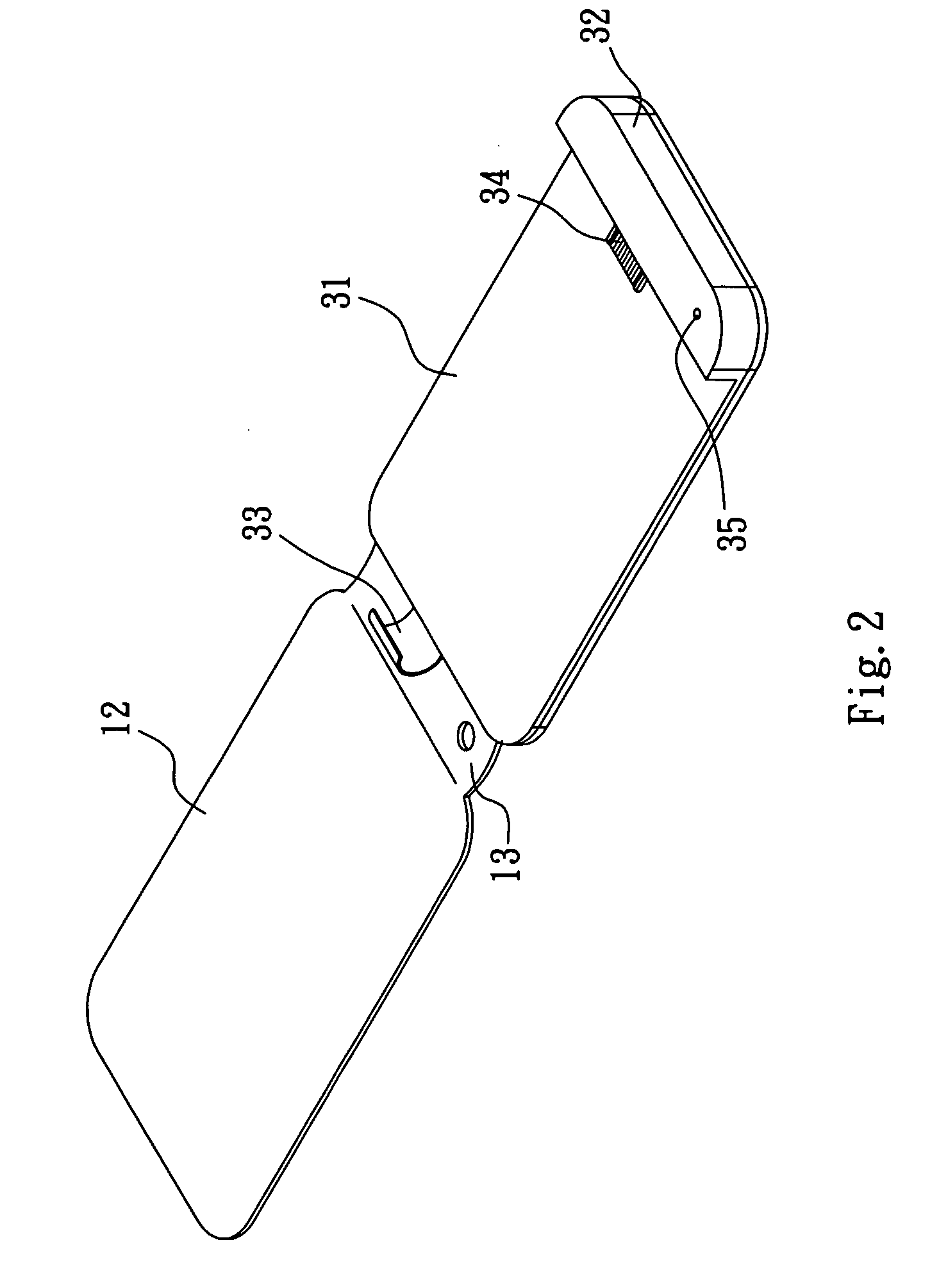
[0015]Please refer to FIGS. 1 and 2 that are exploded and assembled front perspective views, respectively, of a protective cover with power supply unit for portable electronic device according to a preferred embodiment of the present invention, and to FIG. 3 that is a rear view of FIG. 2. As shown, the protective cover of the present invention includes a covering unit 1, a power supply unit 2, and a fixing unit 3.

[0016]The covering unit 1 includes a back cover 11 and a front cover 12 connected end to end via an interconnecting section 13 located therebetween. In a preferred embodiment, the covering unit 1 is made of a leather material.

[0017]The power supply unit 2 is associated with the covering unit 1, and includes a charging battery 21 embedded in the back cover 11, and a connector 22 located at a predetermined position on an outer side of the back cover 11 to electrically connect to the charging battery 21.

[0018]The fixing unit 3 is associated with the covering unit 1, and includ...


PUM


Abstract

A protective cover with power supply unit for portable electronic device includes a covering unit having a back and a front cover; a power supply unit including a charging battery embedded in the back cover and a connector located on an outer side of the back cover at a predetermined position to electrically connect to the charging battery; and a fixing unit including a supporting plate fixed to an inner side of the back cover, a stop block formed on the supporting plate at a lower end thereof, a holding-down element located on the supporting plate at an upper end thereof opposite to the stop block, and a mating connector provided on the stop block and electrically connected to the charging battery. A portable electronic device may be connected to the fixing unit to obtain power from the power supply unit and be protected by the covering unit against damage.

Description


Claims


Application Information

Patent Timeline
Owner LIU KENG YUAN
Why Eureka
Try Eureka