Image pickup device, image blur correcting method, and program

a pickup device and blur correction technology, applied in the field of image pickup devices, can solve the problems of inability to achieve efficient blur correction, power consumption increase, and inability to achieve control between the two processes, so as to reduce power consumption, reduce power consumption, and reduce image degradation.

Inactive Publication Date: 2009-12-24
SONY CORP
View PDF18 Cites 67 Cited by
  • Summary
  • Abstract
  • Description
  • Claims
  • Application Information

AI Technical Summary

Benefits of technology

[0013]Accordingly, the present invention has been proposed in view of such an actual situation, and it is desirable to provide an image pickup device, an image blur correcting method, and a program that make it possible to secure a sufficient correction margin even for an image blur of large amplitude, and perform efficient image blur correction.
[0017]The image pickup device according to the above-described embodiment of the present invention can separate a detected image blur signal into different frequency bands, and perform a correction process by an optical image blur correction process and an electronic image blur correction process. Therefore, a sufficient correction margin can be secured even for image blurs of large amplitude, and the optical image blur correction process is performed for image blurs of small amplitude. It is thus possible to minimize power consumption, and perform a correction process with little image degradation.

Problems solved by technology

Therefore control cannot be performed with consistency achieved between the two processes.
When the processes are thus performed independently each other, power consumption is increased, and efficient blur correction cannot be achieved.

Method used


Image

  • Image pickup device, image blur correcting method, and program
  • Image pickup device, image blur correcting method, and program
  • Image pickup device, image blur correcting method, and program

Examples


Embodiment Construction

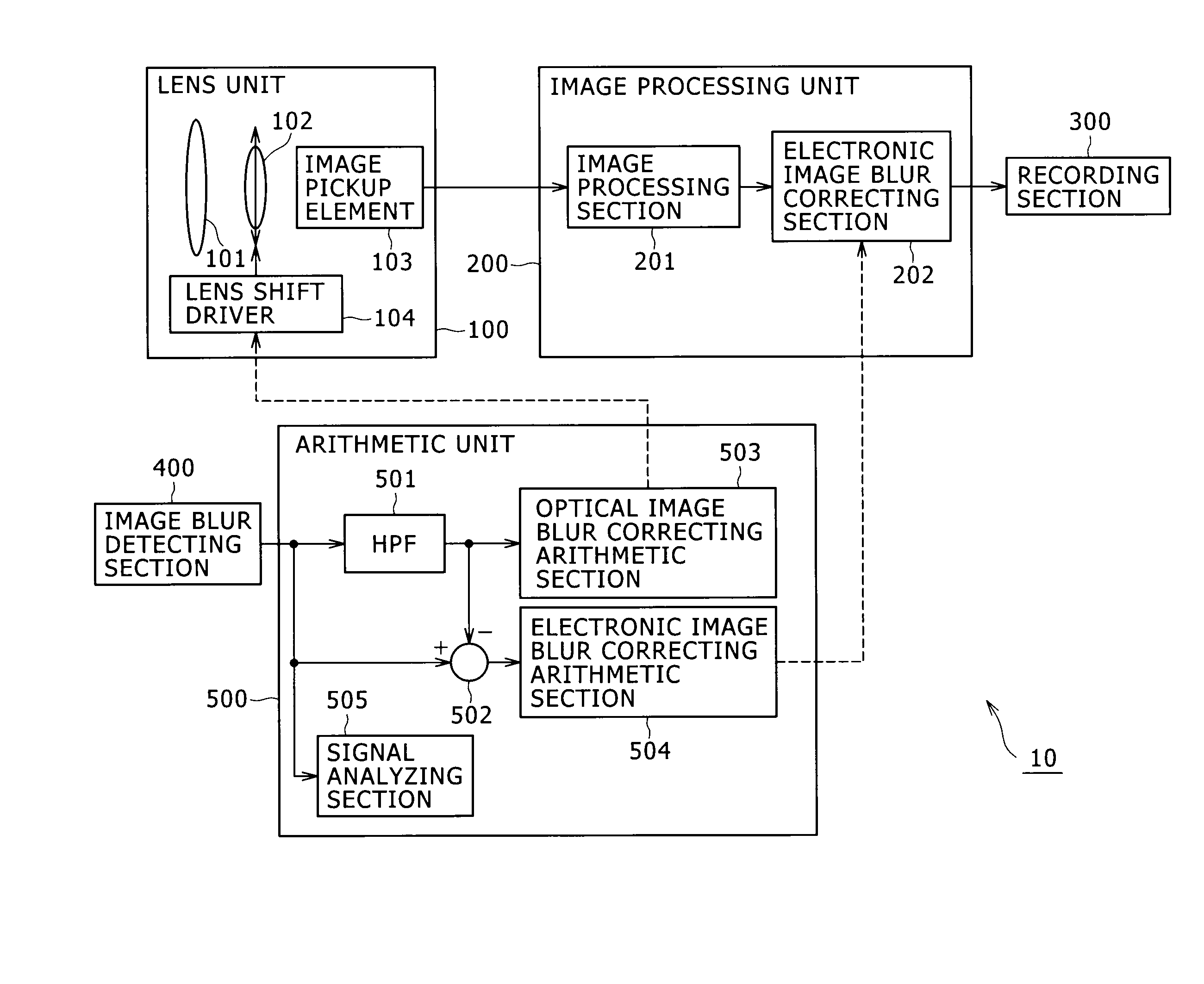
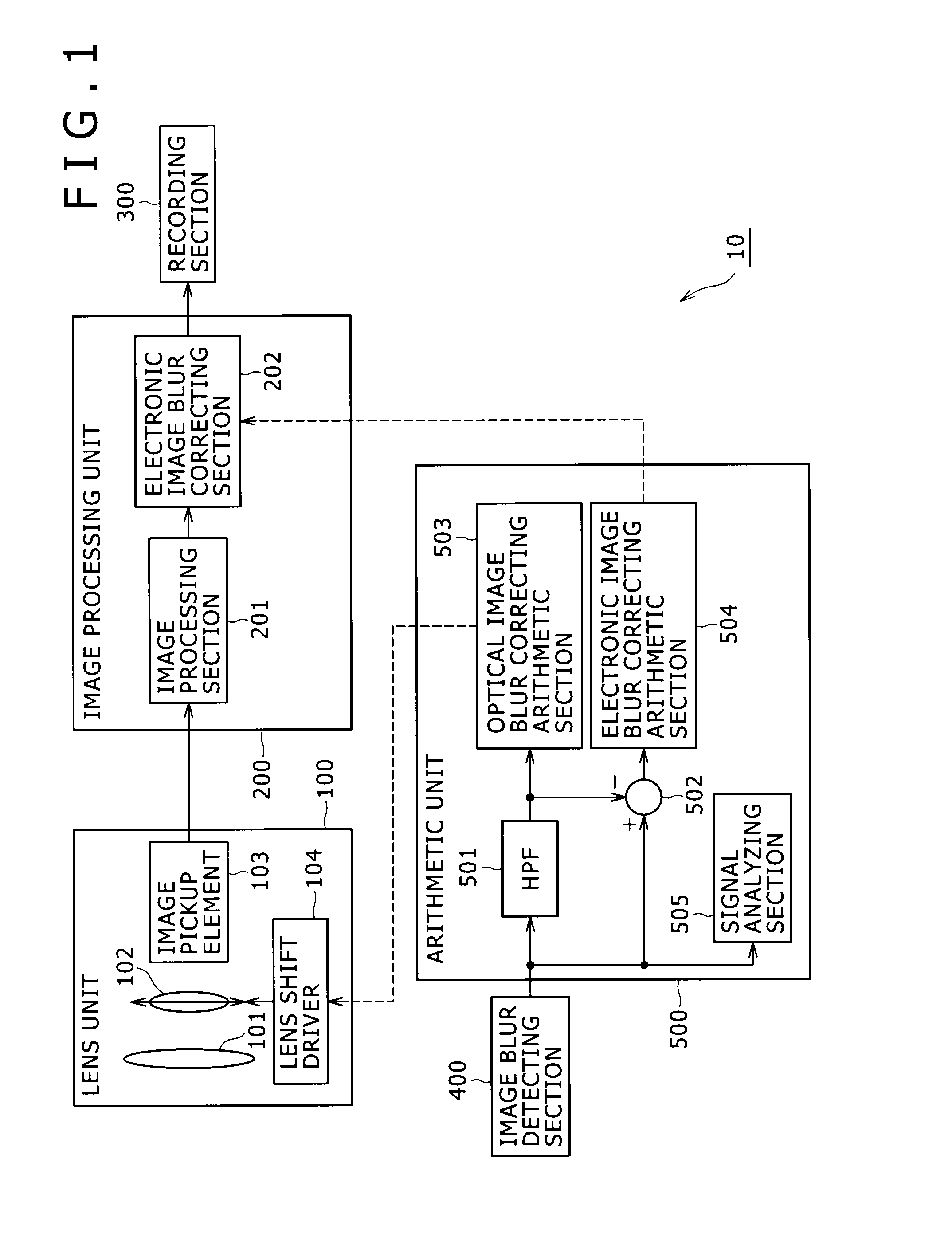
[0033]An image pickup device according to an embodiment will hereinafter be described in detail with reference to the drawings.

[0034]FIG. 1 is a diagram showing a system configuration of the image pickup device according to the present embodiment. As shown in FIG. 1, the image pickup device 10 includes: a lens unit 100 for forming a subject image and reading out an image signal corresponding to the subject image; an image processing unit 200 for performing image processing on the image signal read out from the lens unit 100; a recording section 300 for recording image data; an image blur detecting section 400 for detecting an image blur signal using a sensor for detecting movement; and an arithmetic unit 500 for calculating an amount of correction for correcting the image blur signal detected by the image blur detecting section 400.

[0035]The lens unit 100 is an image pickup optical system that includes a plurality of optical elements and an image pickup element, and which forms a su...


PUM


Abstract

An image pickup device includes: an image pickup optical system configured to form a subject image; an image pickup element configured to generate a picked-up image from the subject image formed by the image pickup optical system; an image blur detecting section configured to output an image blur signal using a motion detecting sensor; an arithmetic section configured to calculate an amount of image blur correction including an amount of optical correction and an amount of electronic correction on a basis of the image blur signal; an optical image blur correcting section configured to move at least one of an optical element forming a part of the image pickup optical system and the image pickup element in accordance with the amount of optical correction; and an electronic image blur correcting section configured to correct electronically an image blur of the picked-up image by image processing based on the amount of electronic correction.

Description

BACKGROUND OF THE INVENTION[0001]1. Field of the Invention[0002]The present invention relates to an image pickup device, an image blur correcting method, and a program that can efficiently process an image blur caused by a vibration or the like.[0003]2. Description of the Related Art[0004]An image picked up by an image pickup device such as a digital camera or the like may have a blur, or a so-called hand movement blur, of a subject image due to for example the shaking of the hand of a user holding the body of a camera at a time of image pickup. Therefore the digital camera incorporates a correcting function for correcting the blur of the subject image (hereinafter referred to as an “image blur”) appearing in the picked-up image due to a vibration applied to the body of the camera, including the hand movement of the user.[0005]An optical image blur correction process and an electronic image blur correction process have been known as image blur correction process, and the image blur ...

Claims


Application Information

Patent Timeline
Patent Type & Authority Applications(United States)
IPC IPC(8): H04N5/228
CPCG03B5/00G03B2217/005H04N5/23287H04N5/23258H04N5/23248H04N23/68H04N23/6812H04N23/687
Inventor NOMURA, HIROFUMI
Owner SONY CORP
Why Eureka
Try Eureka