Magnetic head assembly and magnetic recording apparatus

a magnetic recording and head assembly technology, applied in special recording techniques, maintaining head carrier alignment, instruments, etc., can solve the problems of difficult realization of such high recording density, slowing down of the increase of recording density, and difficulty in efficiently applying high-frequency magnetic field to the medium

Active Publication Date: 2009-12-24
KK TOSHIBA
View PDF13 Cites 59 Cited by
  • Summary
  • Abstract
  • Description
  • Claims
  • Application Information

AI Technical Summary

Problems solved by technology

However, in the 2000s, the problem of thermal fluctuation of the magnetic recording media has been actualized and therefore the speed of the increase of the recording density has temporarily slowed down.
However, it is thought that realization of such high recording density is not easy even by using the perpendicular magnetic recording scheme because the problem of thermal fluctuation is actualized again.
However, in the technique disclosed in U.S. Pat. No. 6,011,664, the high-frequency magnetic field is generated by a coil and therefore it has been difficult to efficiently apply the high-frequency magnetic field to the medium.
However, the former measures are not desirable because the spin torque efficiency falls.
Moreover, the latter measures involves technically large difficulty because a floatation amount from the recording medium surface of the head slider on which the magnetic recording head is mounted is currently about 10 nm.

Method used


Image

  • Magnetic head assembly and magnetic recording apparatus
  • Magnetic head assembly and magnetic recording apparatus
  • Magnetic head assembly and magnetic recording apparatus

Examples


first embodiment

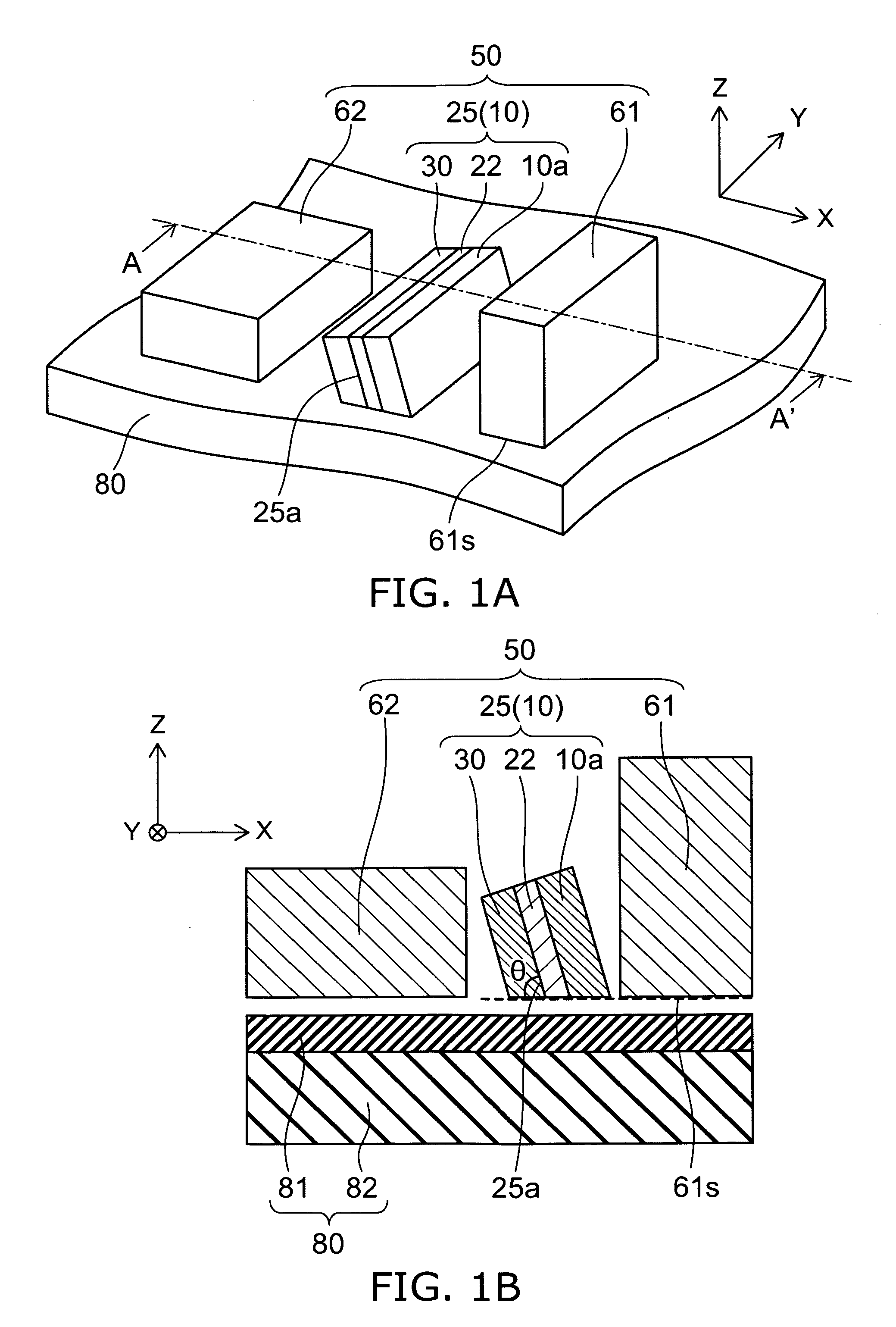
[0044]FIGS. 1A and 1B are schematic views illustrating the configuration of magnetic recording head according to a first embodiment of the invention.

[0045]Namely, FIG. 1A is a schematic perspective view, and FIG. 1B is a cross-sectional view taken along line A-A′ of FIG. 1A.

[0046]In the figures, in addition of the magnetic recording head according to the first embodiment of the invention, a magnetic recording medium for performing magnetic recording by a magnetic recording head is also drawn.

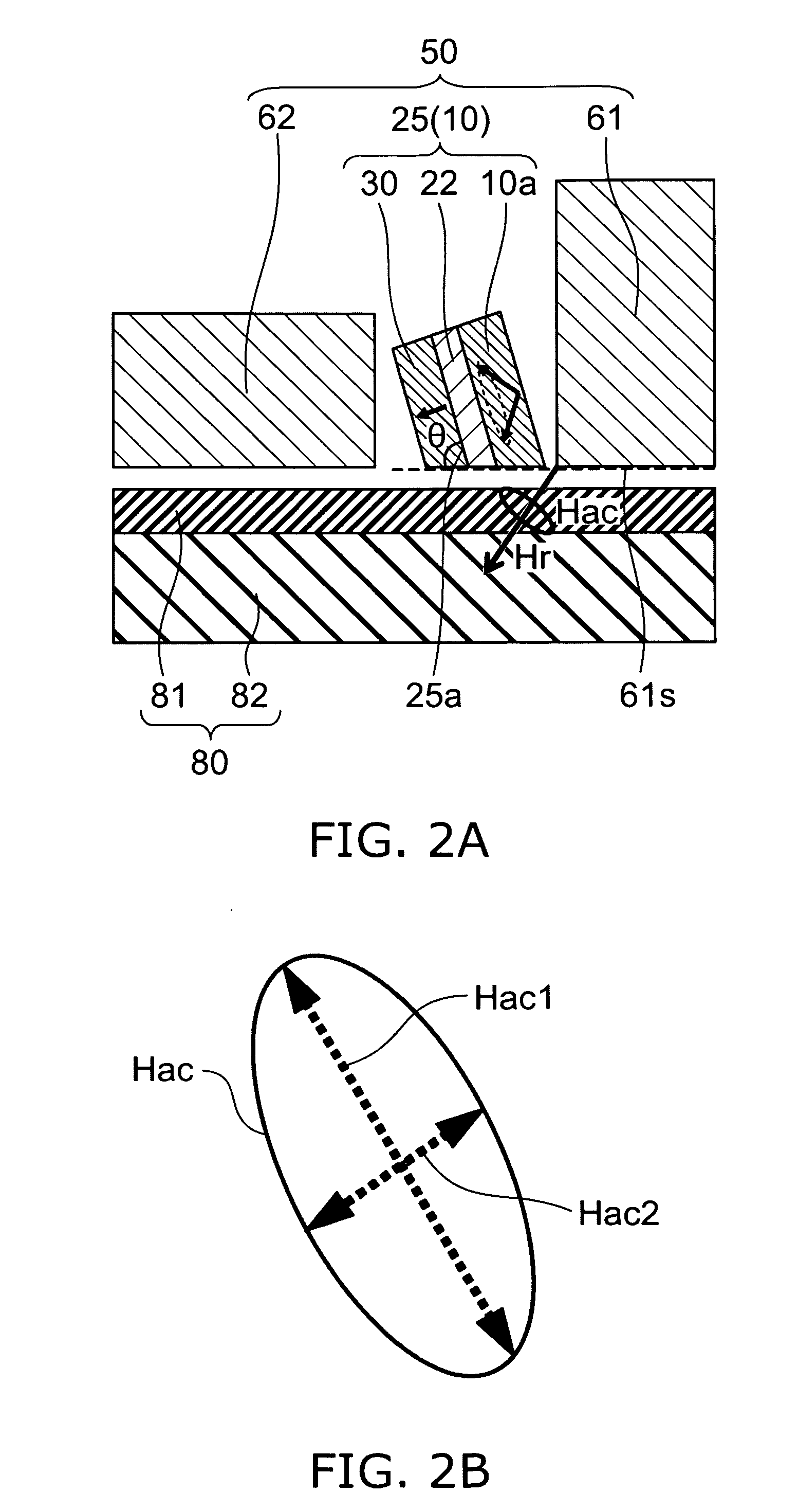
[0047]As shown in FIGS. 1A and 1B, the magnetic recording head 50 according to the first embodiment of the invention has a main magnetic pole 61 and a stacked structure 25.

[0048]The stacked structure 25 has an oscillation layer (first magnetic layer) 10a, a spin injection layer 30 (second magnetic layer), and an intermediate layer 22 provided between the oscillation layer 10a and the spin injection layer 30.

[0049]The main magnetic pole 61 has an air bearing surface 61s facing a magnetic recordin...

second embodiment

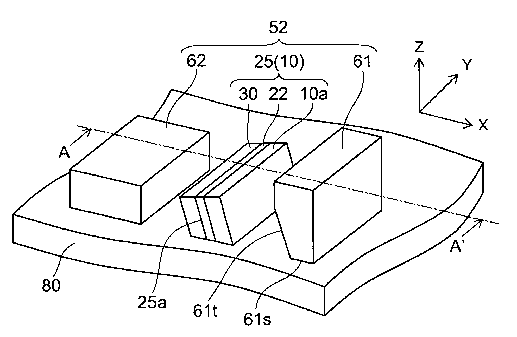
[0126]FIGS. 15A and 15B are schematic views illustrating the configuration of the magnetic recording head according to the second embodiment of the invention.

[0127]That is, FIG. 15A is a schematic perspective view, and FIG. 15B is a cross-sectional view taken along A-A′ of FIG. 15A.

[0128]As shown in FIGS. 15A and 15B, in the magnetic recording head 52 according to the second embodiment of the invention, the surface 61t of the main magnetic pole 61 facing the stacked structure 25 is inclined so as to be along the stacked plane 25a of the stacked structure 25.

[0129]That is, in the magnetic recording head 52 according to this embodiment, the stacked plane 25a of the stacked structure 25 is inclined with respect to the air bearing surface 61s of the main magnetic pole 61, and furthermore, the surface 61t of the main magnetic pole 61 facing the stacked structure 25 is approximately parallel to the stacked plane 25a of the stacked structure 25.

[0130]Other than this, the magnetic recording...

third embodiment

[0154]FIGS. 19A and 19B are schematic views illustrating the configuration of the magnetic recording head according to the third embodiment of the invention.

[0155]That is, FIG. 19A is a schematic perspective view, and FIG. 19B is a cross-sectional view taken along line A-A′ of FIG. 19A.

[0156]As shown in FIGS. 19A and 19B, the magnetic recording head 53 according to the third embodiment of the invention includes, the main magnetic pole 61 having the air bearing surface 61s facing the magnetic recording medium, and the stacked structure 25 having the oscillation layer 10a, the spin injection layer 30, and the intermediate layer 22 provided between the oscillation layer 10a and the spin injection layer 30. The orientation axis 10p of the oscillation layer 10a is inclined with respect to the air bearing surface 61s. In the specific example illustrated in FIGS. 19A and 19B, the orientation axis 10p of the oscillation layer 10a is inclined with respect to the air bearing surface 61s. Howe...


PUM

PropertyMeasurementUnit
angleaaaaaaaaaa
angleaaaaaaaaaa
inclination angleaaaaaaaaaa

Abstract

A magnetic head assembly includes a magnetic recording head, a main magnetic pole, a head slider, a suspension and an actuator arm. The magnetic recording head includes a main magnetic pole having an air bearing surface facing a magnetic recording medium; and a stacked structure having, a first magnetic layer, a second magnetic layer, and an intermediate layer provided between the first magnetic layer and the second magnetic layer. A stacked plane of the stacked structure is inclined with respect to the air bearing surface. The magnetic recording head is mounted on the head slider. The head slider is mounted on one end of the suspension. The actuator arm is connected to the other end of the suspension.

Description

CROSS-REFERENCE TO RELATED APPLICATIONS[0001]This application is based upon and claims the benefits of priority from the prior Japanese Patent Application No. 2008-161024, filed on Jun. 19, 2008; the entire contents of which are incorporated herein by reference.BACKGROUND OF THE INVENTION[0002]1. Field of the Invention[0003]This invention relates to a magnetic head assembly and a magnetic recording apparatus.[0004]2. Background Art[0005]In the 1990s, practical application of MR (Magneto-Resistive effect) head and GMR (Giant Magneto-Resistive effect) head has acted as a trigger for recording density and recording capacity of HDD (Hard Disk Drive) to be drastically increased. However, in the 2000s, the problem of thermal fluctuation of the magnetic recording media has been actualized and therefore the speed of the increase of the recording density has temporarily slowed down. Even so, perpendicular magnetic recording, which is fundamentally more advantageous than the longitudinal magn...

Claims


Application Information

Patent Timeline
Patent Type & Authority Applications(United States)
IPC IPC(8): G11B5/60G11B5/127
CPCG11B5/02G11B5/1278G11B2005/0005G11B5/3153G11B5/314
Inventor FUNAYAMA, TOMOMIYAMADA, KENICHIROKOUI, KATSUHIKOIWASAKI, HITOSHITAKAGISHI, MASAYUKITAKASHITA, MASAHIROSHIMIZU, MARIKOOIKAWA, SOICHI
Owner KK TOSHIBA
Why Eureka
Try Eureka