Transmission system

a transmission system and high voltage direct current technology, applied in the direction of circuit arrangements, electrical power transfer ac networks, arrangements resposes to fault current, etc., can solve the problem of not being able to transmit any current or power for monopolar operation, causing instabilities in the system, and causing failures in other parts. problems, to achieve the effect of reducing the risk of major disturbances

Inactive Publication Date: 2009-12-24
ABB POWER GRIDS SWITZERLAND AG
View PDF3 Cites 20 Cited by
  • Summary
  • Abstract
  • Description
  • Claims
  • Application Information

AI Technical Summary

Benefits of technology

[0010]The object of the present invention is to provide a HVDC transmission system of the type defined in the introduction, in which the risks of major disturbances on an AC system connected thereto upon monopolar trip of the HVDC transmission system are substantially reduced.
[0012]Would an earth fault occur in one electrode line, this earth fault may be isolated and monopolar operation of the transmission system may be maintained by connecting the “healthy” neutral bus to the other electrode line or electrode lines. Furthermore, by dimensioning the electrode lines in this way substantially full monopolar power, i.e. half bipolar power, may still be transmitted reducing the risk of such a large impact upon the AC system connecting to the HVDC transmission system that disturbances having serious consequences result in said AC system. Another advantage of the transmission system according to the invention is that maintenance of one electrode line including other equipment associated therewith is possible during both bipolar operation and monopolar operation with earth return without reduction of power transmission capability.
[0014]According to another embodiment of the invention the transmission system has for a said DC neutral arrangement at least three said electrode lines, and in the case of exactly three electrode lines each may be dimensioned to be able to transmit substantially half said full current. These embodiments are favourable when the electrode lines have to extend over long distances, since a material saving of about 25% in the case of three said electrode lines instead of two may result in a remarkable saving of material costs in such a case.
[0018]According to another embodiment of the invention said DC neutral arrangement comprises an additional second DC breaker connected in series with said first DC breaker in said first current path between said two neutral buses for bipolar operation of the station. This means that these two DC breakers connected in series will function as backup for each other when the current path is to be opened for diverting the current to the electrode station, so that it may be avoided to close a grounding switch if one of the breakers will not be able to bring the current through it down to zero.

Problems solved by technology

This means that the consequence for the connected AC systems can be very severe if both poles of the transmission line would be tripped, i.e. be disconnected as a consequence of for instance an earth fault, at the same time.
If a said AC system belongs to a major system providing a large city with electric power such a bipolar trip may result in such a large reduction of the electric power supplied to said major system, that instabilities may be created in that system and other parts may then also fail.
The DC neutral arrangement of such a known converter station provides a quite good reliability but has still some drawbacks.
Furthermore, if an earth fault occur on one of the electrode lines it is not possible to transmit any current or power for monopolar operation with earth return.
Thus, if an earth fault occurs on one of the electrode lines no power at all may be delivered during this period of time.
Thus, one of the poles is then first tripped and the other pole is tripped very shortly thereafter due to said earth fault on the electrode line, which can be difficult to detect until current is flowing through the electrode lines, and a major disturbance may then result in the AC system connecting to the HVDC transmission system due to the bipolar trip of the latter system.
At the moment when a transfer from earth return to metallic return may then be carried out it will be too late for avoiding major problems in the AC system.

Method used


Image

  • Transmission system
  • Transmission system
  • Transmission system

Examples


Embodiment Construction

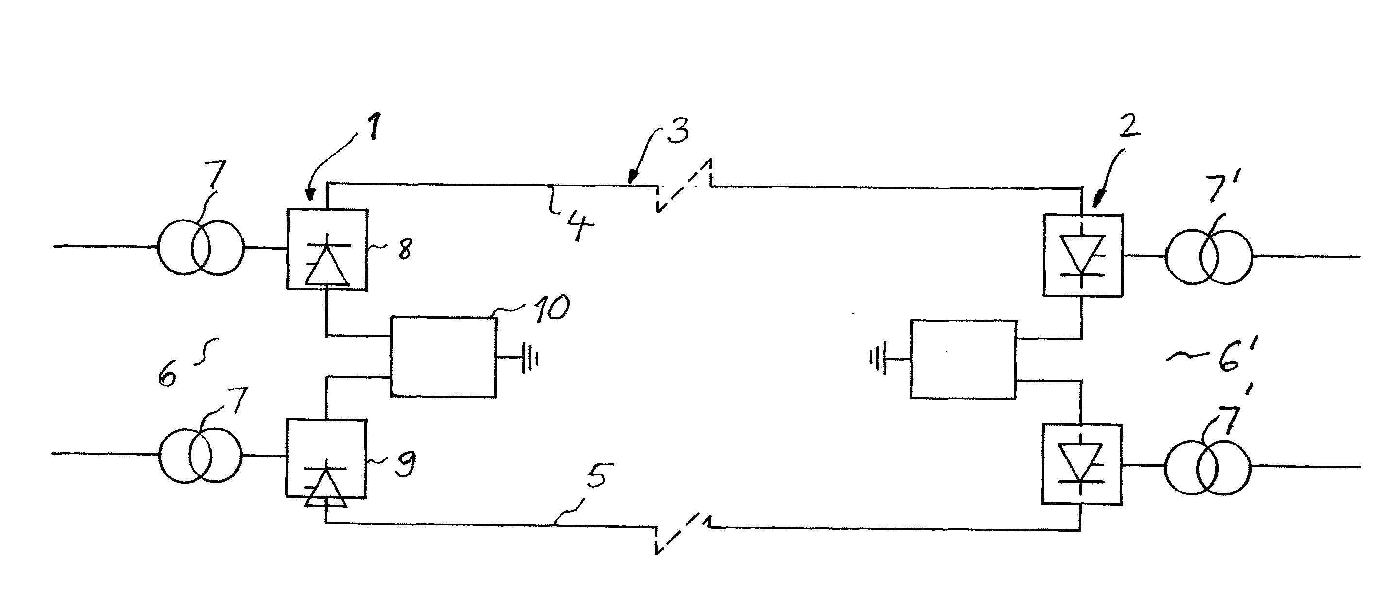
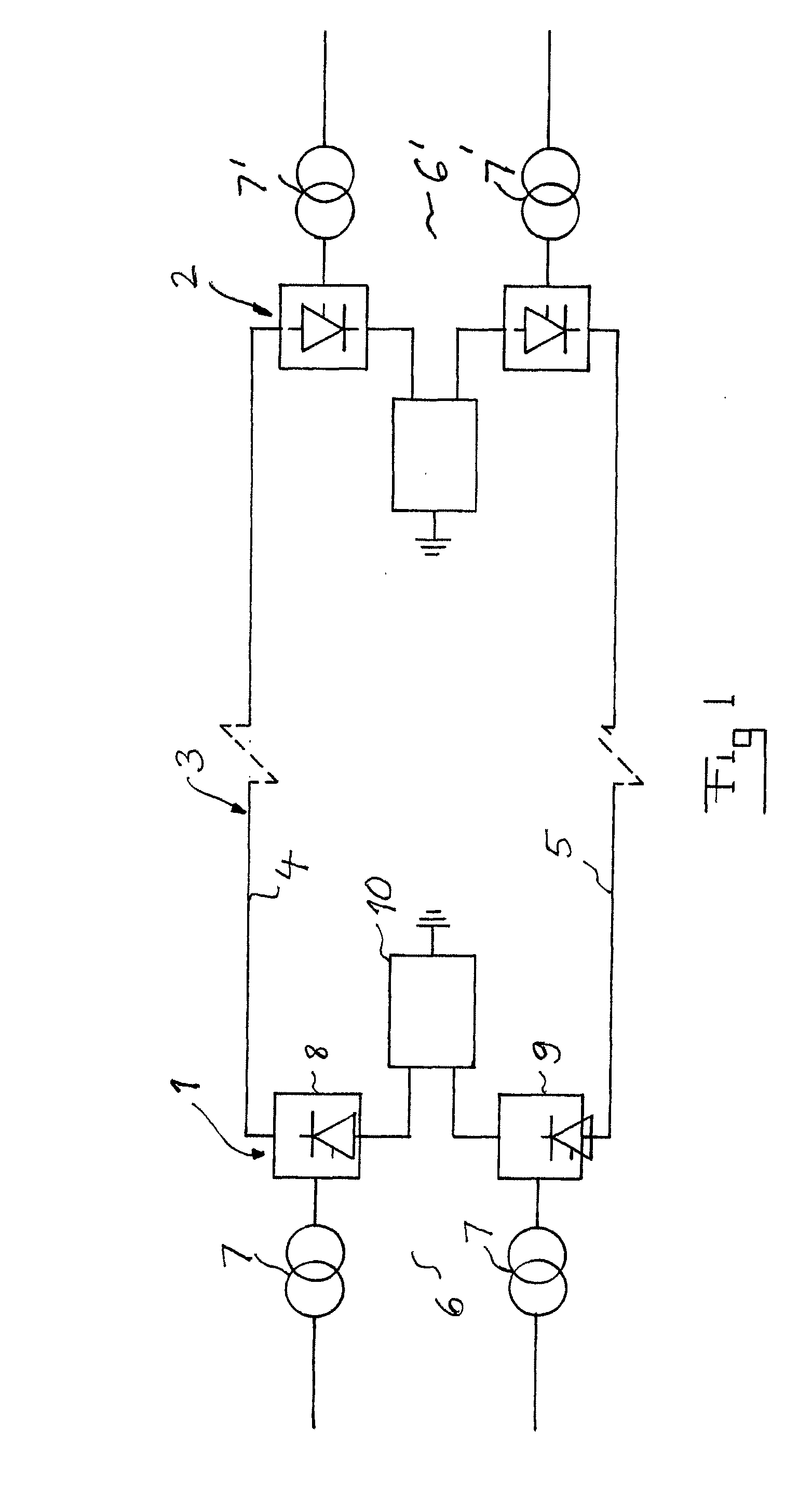
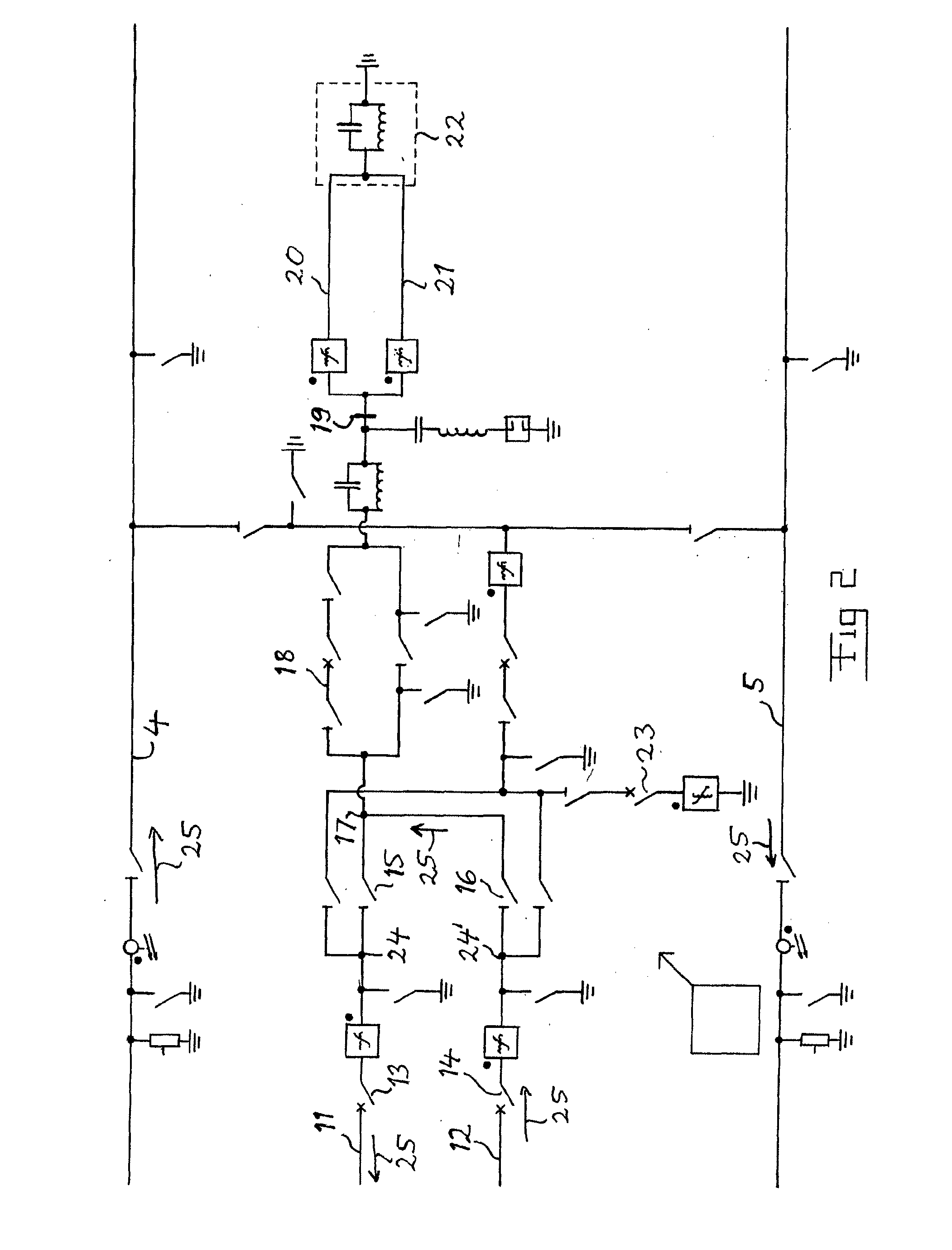
[0031]The two poles of a HVDC transmission system according to an embodiment of the invention are here designated by 104 and 105 and the two neutral buses of a DC neutral arrangement thereof by 111 and 112. The poles are here intended to have a polarity of e.g. +800 kV and −800 kV, respectively. The neutral buses 111, 112 are connected to each other through a first current path 130, in which a first DC breaker 131 and a second DC breaker 132 are connected in series. Each of these DC breakers are surrounded by two disconnectors 133-136.

[0032]Each neutral bus is further through a first line 140, 141 connected to one of two separate electrode line connecting members 142, 143, each of which being connected to a separate electrode line 191, 192 and by that to an electrode station 190, which may be located several kilometres away from the converter station to which said connecting members 142, 143 belong. Each of the electrode lines 191, 192 is dimensioned to be able to alone transmit ful...


PUM


Abstract

A HVDC transmission system including at one end of a bipolar HVDC transmission line a converter station for connecting the transmission line to an AC system. The station has two converters and a DC neutral arrangement in common to the converters. The DC neutral arrangement has a separate electrode line connecting member connecting to electrode lines. The electrode lines are dimensioned to be able to at monopolar operation of the converter station transmit substantially full current to an electrode station through the remaining one or ones of the electrode lines at disconnection of an arbitrary of the electrode lines.

Description

TECHNICAL FIELD OF THE INVENTION AND PRIOR ART[0001]The present invention relates to a HVDC (High Voltage Direct Current) transmission system comprising at one end of a bipolar HVDC transmission line a converter station for connecting said transmission line to an AC-system, said station comprising two converters each having a DC-side thereof connected on one hand to a respective of two poles of said transmission line on high potential and on the other to a neutral bus for that pole of a DC neutral arrangement in common to the converters on zero potential by being earthed, and each said converter having an AC-side connected to said AC system, said DC neutral arrangement having a member connecting to electrode lines and the arrangement being provided with first DC breakers enabling breaking of a first current path from the neutral bus of one pole to the neutral bus of the other pole at bipolar operation of the station for changing to monopolar operation thereof, said station also comp...

Claims


Application Information

Patent Timeline
IPC IPC(8): H02J3/36
CPCH02H7/268H02H3/16Y02E60/60H02J3/36H02H3/17H02H5/105H02H11/001
Inventor ASTROM, URBANRADBRANT, ULF
Owner ABB POWER GRIDS SWITZERLAND AG
Why Eureka
Try Eureka