Contact-free vehicle air vent

a technology of contact-free air vents and vehicles, which is applied in the direction of vessel parts, transportation and packaging, vessel construction, etc., can solve the problem of dangerous momentary re-focusing of the driver's attention away from the road

Inactive Publication Date: 2009-12-24
NISSAN MOTOR CO LTD
View PDF17 Cites 31 Cited by
  • Summary
  • Abstract
  • Description
  • Claims
  • Application Information

AI Technical Summary

Benefits of technology

[0006]One object of the present invention is to allow a driver to change air flow direction from a vehicle air vent without having to touch or make contact with either a switch or the air vent.

Problems solved by technology

Even a momentary re-focusing of the driver's attention away from the road can be dangerous.

Method used


Image

  • Contact-free vehicle air vent
  • Contact-free vehicle air vent
  • Contact-free vehicle air vent

Examples


second embodiment

[0068]Referring now to FIG. 12, a contact-free air vent 112 in accordance with a second embodiment will now be explained. In view of the similarity between the first and second embodiments, the parts of the second embodiment that are identical to the parts of the first embodiment will be given the same reference numerals as the parts of the first embodiment. Moreover, the descriptions of the parts of the second embodiment that are identical to the parts of the first embodiment may be omitted for the sake of brevity.

[0069]In the second embodiment, the contact-free air vent 112 has many of the same features as in the first embodiment, such as the outer housing 22, the plurality of vertically oriented air blades 24, the plurality of horizontally oriented air blades 26, the first servo device 28 and the second servo device 30. However, in the second embodiment the first pair of sensors 34 has been replaced with a sensor array 134, the second pair of sensors 36 has been replaced with a s...

third embodiment

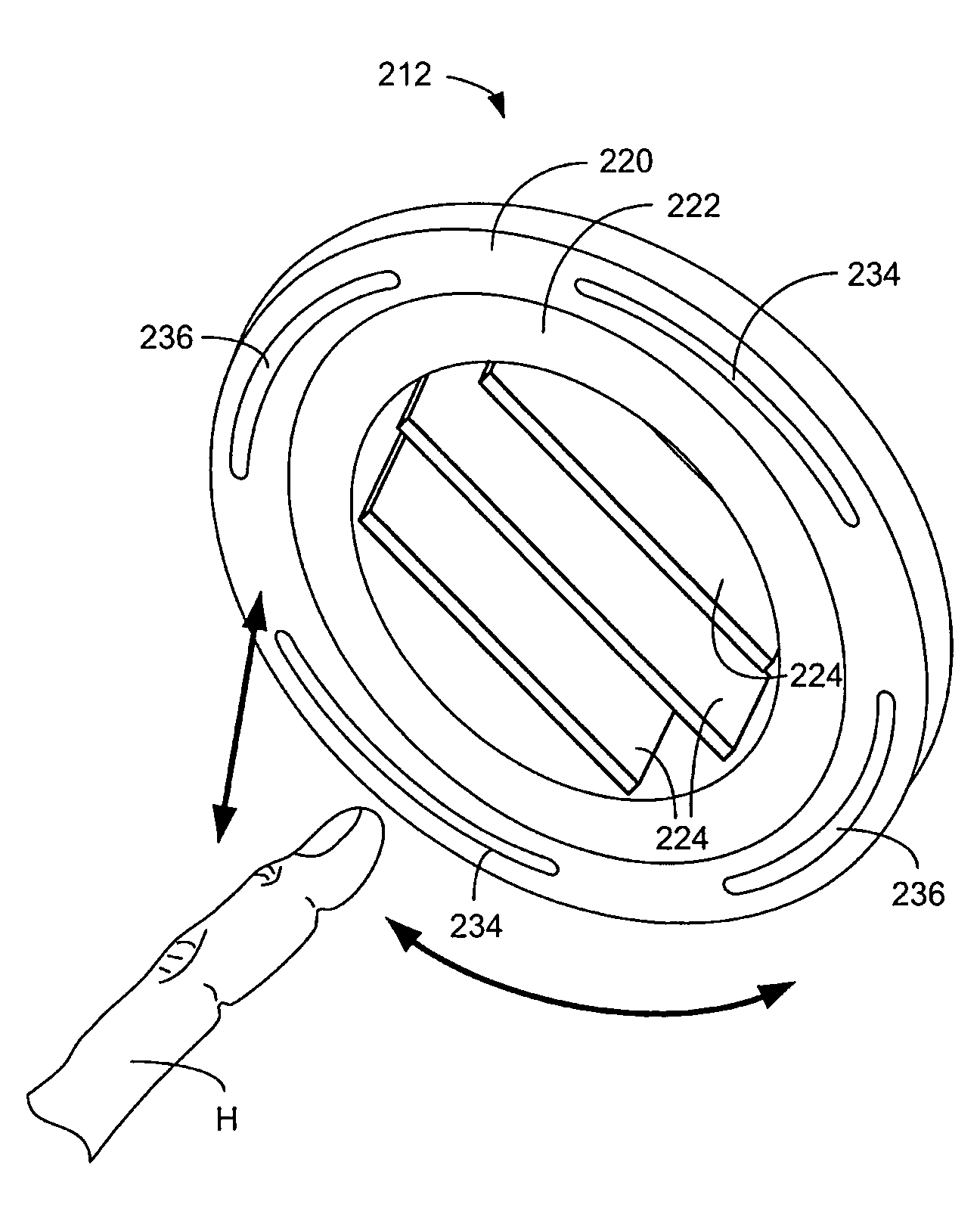
[0077]Referring now to FIG. 13-17, a contact-free air vent 212 in accordance with a third embodiment will now be explained. In view of the similarity between the first and third embodiments, the parts of the third embodiment that are identical to the parts of the first embodiment will be given the same reference numerals as the parts of the first embodiment. Moreover, the descriptions of the parts of the third embodiment that are identical to the parts of the first embodiment may be omitted for the sake of brevity.

[0078]In the third embodiment, the contact-free air vent 212 includes a fixed housing 220 and a rotatable housing 222 that supports a plurality of the flow control blades 224, a positioning mechanism that includes a first servo device 228 and a second servo device 230, a first pair of sensors 234, a second pair of sensors 236 and a controller 238 (a control unit).

[0079]The fixed housing 220 is attachable to the dashboard 14 in a manner similar to the attachment of the oute...


PUM


Abstract

A contact-free air vent flow direction control device includes an air vent, a positioning mechanism, a touch-less motion sensor and a control unit. The air vent has at least one flow control blade configured to move between a plurality of predetermined orientations each corresponding to a direction of air flow from the air vent. The positioning mechanism is operably coupled to the flow control blade. The touch-less motion sensor is configured to detect relative movement of objects proximate the touch-less motion sensor. The control unit is operably connected to the touch-less motion sensor and the positioning mechanism to control operation of the positioning mechanism in order to position the flow control blade in a selected one of the predetermined orientations in response to a corresponding one of a plurality of predetermined movements detected by the touch-less motion sensor.

Description

BACKGROUND OF THE INVENTION[0001]1. Field of the Invention[0002]The present invention relates to a vehicle contact-free air vent. More specifically, the present invention relates to vehicle air vent configured such that adjustments of direction of air flow are made without contact by the vehicle driver or passenger.[0003]2. Background Information[0004]Safety concerns are of paramount importance in the design of new features for automotive vehicles. One area of concern relates to the various features of a vehicle that must be touched and manipulated by a vehicle driver, such as a vehicle's air conditioning system controls. In order for a driver to change the speed of the blower motor fan or the direction of air flowing out of an air vent, the driver must briefly focus his or her attention on the blower motor fan control and / or the blades of the air vent. Even a momentary re-focusing of the driver's attention away from the road can be dangerous.[0005]In view of the above, it will be a...

Claims


Application Information

Patent Timeline
Patent Type & Authority Applications(United States)
IPC IPC(8): B60H1/34
CPCB60H2001/3471B60H1/3428B60H1/00742
Inventor KONET, HEATHER
Owner NISSAN MOTOR CO LTD
Why Eureka
Try Eureka