Device And Method For Contact Free Absolute Position Determination

a technology of absolute position determination and device, which is applied in the field of contact free arrangement, can solve the problems of not being able unable to adapt to contact free and absolute position determination, and unable to perform absolute position measurements in contact free mode of operation

Active Publication Date: 2009-03-19
NOVO NORDISK AS
View PDF103 Cites 30 Cited by
  • Summary
  • Abstract
  • Description
  • Claims
  • Application Information

AI Technical Summary

Problems solved by technology

It is a disadvantage of the arrangement suggested in US 2004 / 0207385 that the emitter and receiver electrodes are positioned in a manner where they take up an unnecessary amount of space.
Furthermore, the arrangement suggested in US 2004 / 0207385 is not adapted for contact free and absolute position determination.
Thus, it is a disadvantage of the arrangement suggested in 2004 / 0207385 that absolute measurements cannot be performed in a contact free mode of operation.
Thus, it is a disadvantage of the arrangement suggested in US 2004 / 0207385 that only relative position measurements between rotor and stator can be performed in a contact free mode of operation.
It is a further disadvantage of the arrangement suggested in US 2004 / 0207385 that the rotor is only allowed to the rotated one revolution if its position needs to be tracked.
Thus, if the rotor of US 2004 / 0207385 is rotated more than one revolution, the signals exclusively obtainable from the electrodes no longer provides an unambiguously determination of the angular position relative to the stator.
Finally, the arrangement suggested in US 2004 / 0207385 suffers from the significant drawback that the capacitance used for determining the angular position of the rotor relative to the stator involves determining a capacitance between at least one rotor electrode and at least one stator electrode.
Providing such electrical access to a rotatably mounted member is certainly not a simple and straight forward process.

Method used


Image

  • Device And Method For Contact Free Absolute Position Determination
  • Device And Method For Contact Free Absolute Position Determination
  • Device And Method For Contact Free Absolute Position Determination

Examples


Embodiment Construction

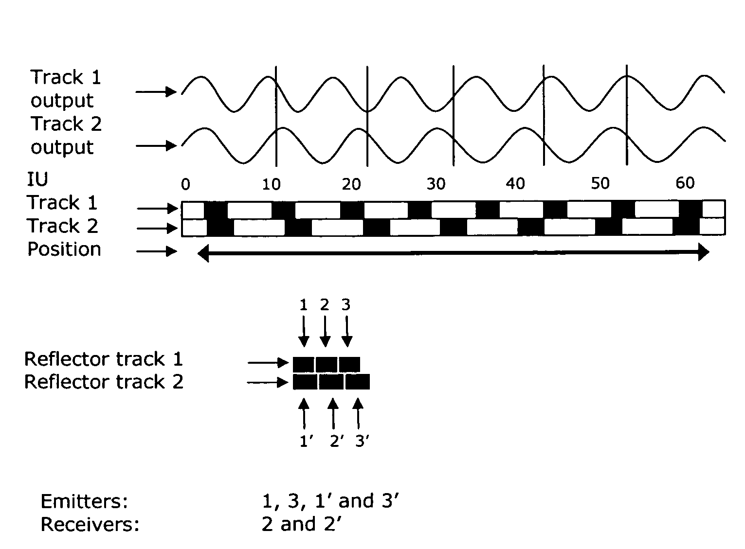
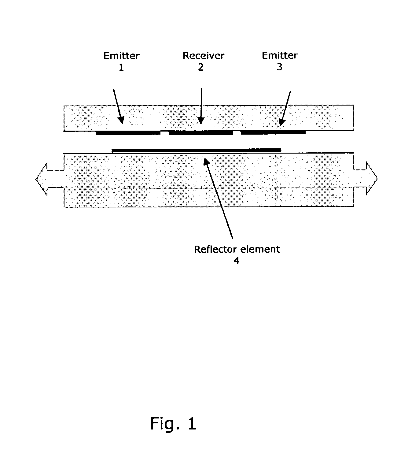
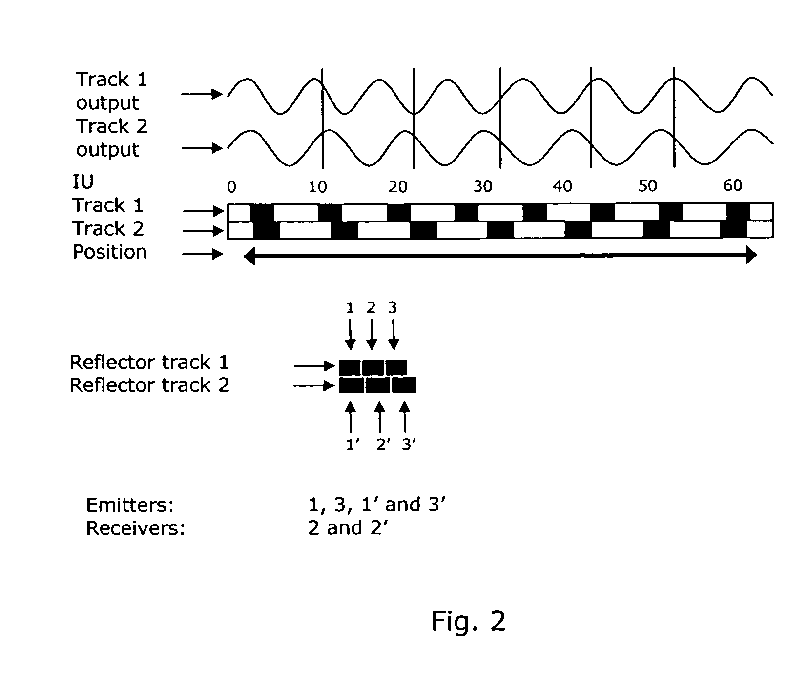
[0059]In its most general aspect, the present invention relates to a contact free position determining arrangement for determining an absolute angular position of a dose setting member of a medication delivery device. The absolute angular position of the dose setting member, which indicates the dose of medicament to be injected from the medication delivery device, is determined by applying information from a capacitive or inductive coupling between emitters and receivers both arranged on a non-rotating member of the medication delivery device, such as the housing of the medication delivery device. The coupling between emitters and receivers is established via reflectors arranged on a rotating member, such as on a dose indicator barrel of the medication delivery device. The reflectors are arranged in one or more tracks having a helical, circular or linear shape. The arrangement according to the present invention can be used for both setting a dose to be injected from the medication d...


PUM


Abstract

The present invention relates to a contact free arrangement for determining an absolute position of a member adapted for setting an amount of medicament to be injected from a medication delivery device, or adapted for determining an amount of medicament injected from a medication delivery device. The arrangement according to the present invention comprises at least one track of reflector means, at least one emitter means, and at least one receiver means. The at least one emitter means and the at least one receiver means are adapted to electrically couple to a number of the reflector means. The electrical coupling may be capacitive or inductive. In addition, the present invention relates to a medication delivery device or a syringe having such arrangement.

Description

FIELD OF THE INVENTION[0001]The present invention relates to a contact free arrangement for determining an absolute position of a member adapted for setting an amount of medicament to be injected from a medication delivery device, or for determining an amount of medicament injected from a medication delivery device. The arrangement according to the present invention comprises at least one track of reflector means, at least one emitter means, and at least one receiver means. The at least one emitter means and the at least one receiver means are adapted to electrically couple to a number of the reflector means. The electrical coupling may be capacitive or inductive. In addition, the present invention relates to a medication delivery device or a syringe having such arrangement incorporated therein.BACKGROUND OF THE INVENTION[0002]U.S. Pat. No. 4,420,754 discloses a system for measuring the relative movement between two elements, such as the scale and slide of a hand-held measuring inst...

Claims


Application Information

Patent Timeline
Patent Type & Authority Applications(United States)
IPC IPC(8): A61M5/31G01B7/14G01D5/241G01D5/20
CPCG01D5/204A61M2205/3317A61M5/31525G01D5/2412G01D5/2403
Inventor NIELSEN, PREBENMUNCHOW, BODO VON
Owner NOVO NORDISK AS
Why Eureka
Try Eureka