

Electric toothbrush
- Summary
- Abstract
- Description
- Claims
- Application Information
AI Technical Summary
Benefits of technology
Problems solved by technology
Method used
Image

Examples
first embodiment
[0017]an electric toothbrush according to the present invention will now be discussed.
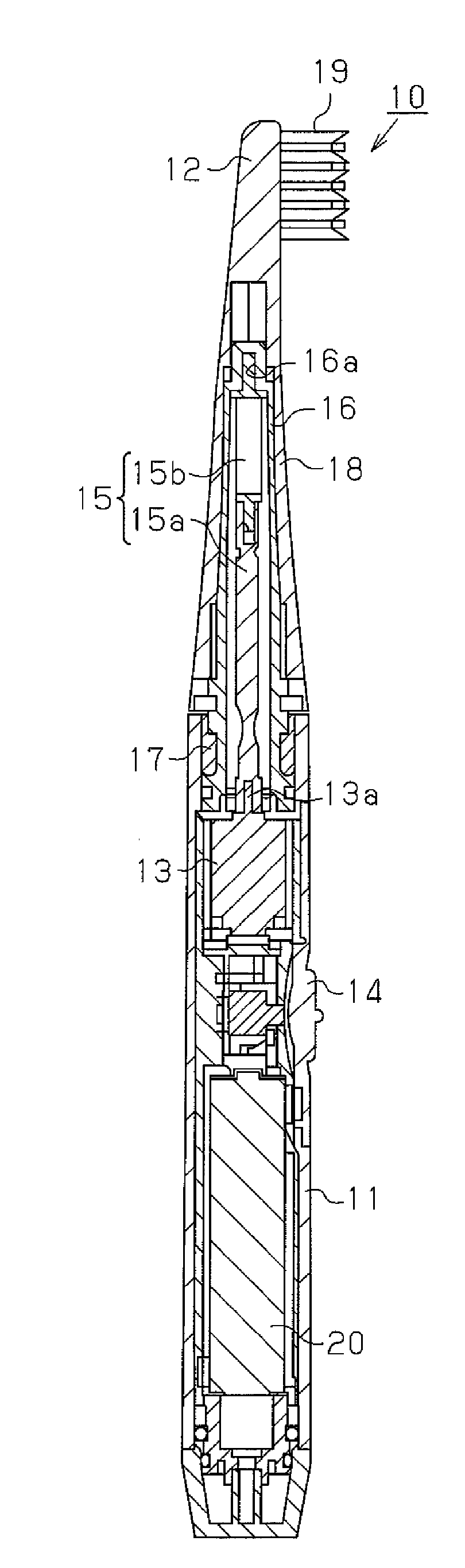
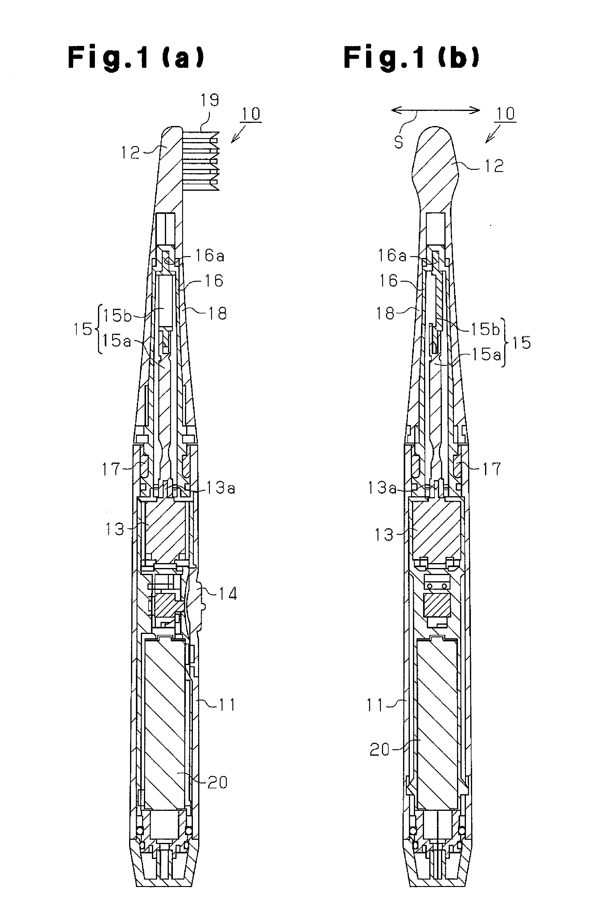
[0018]Referring to FIG. 1, an electric toothbrush 10 includes a grip, or case 11, and a brush unit 12, which is detachably attached to the distal end of the case 11. The case 11 may be elongated and cylindrical. The case 11 accommodates a motor 13 and a battery 20, which supplies power supply voltage. A switch button 14 arranged on the case 11 is used to switch the motor 13 ON and OFF.
[0019]The motor 13 includes a rotary shaft 13a, which extends toward the distal end of the case 11 in the longitudinal direction of the case 11. An eccentric shaft 15 is attached to the rotary shaft 13a. The eccentric shaft 15 includes an elongated main shaft body 15a and a weight 15b, the center of gravity of which is deviated in the radial direction from the axis of the rotary shaft 13a. The weight 15b is attached to the distal end of the main shaft body 15a.
[0020]The eccentric shaft 15 is enclosed in an oscillatio...
second embodiment
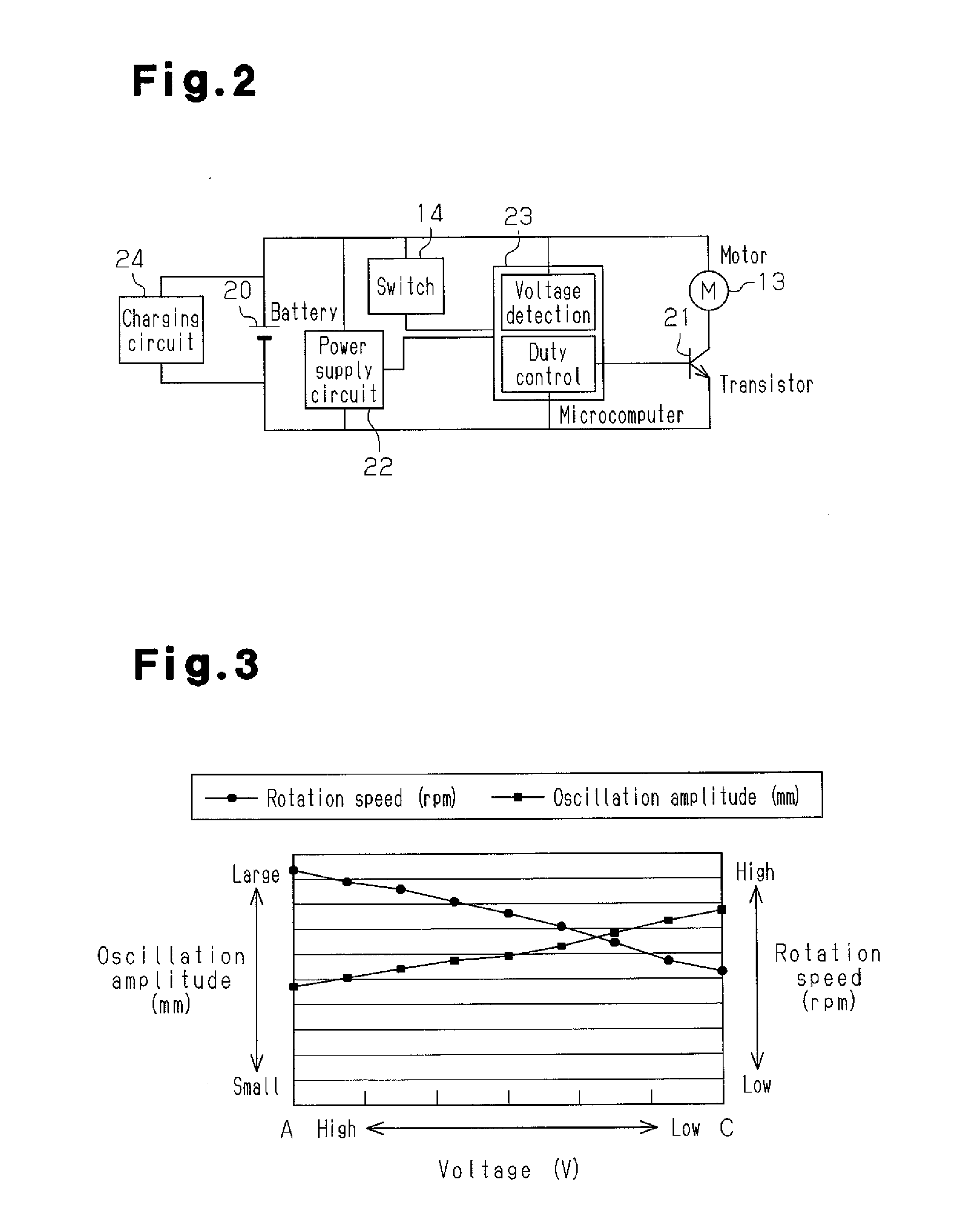
[0038]In the second embodiment, the constant voltage circuit 31 converts the power supply voltage to voltage C (constant voltage), which is shown in FIG. 3. The voltage C is predetermined as a value that is lower than the maximum value A of the power supply voltage and drives the motor 13 at a rotation speed that is high and satisfactory. This allows for the motor 13 to produce high-speed rotations. When the value of the power supply voltage supplied from the battery 20 is higher than the voltage C, the constant voltage circuit 31 converts (lowers) the power supply voltage to the voltage C. When the value of the power supply voltage supplied from the battery 20 decreases to the voltage C or lower, the constant voltage circuit 31 converts (increases) the power supply voltage to the voltage C. This regulates the oscillation amplitude S of the brush portion 19 to be constant regardless of the decrease in the power supply voltage of the battery 20.
[0039]The second embodiment has the sam...
third embodiment
[0040]the present invention will now be discussed.
[0041]Referring to FIG. 6, the motor 13 has one terminal connected to the positive terminal of the battery 20 and another terminal connected to the collector terminal of the transistor 21. The emitter terminal of the transistor 21 is connected to the negative terminal of the battery 20.
[0042]The battery 20 is connected to the power supply circuit 22. The power supply circuit 22 is connected to the control unit 23, which includes a CPU and a RAM. The power supply circuit 22 supplies the control unit 23 with drive voltage that is suitable for driving the control unit 23. The control unit 23 is connected to the battery 20 and detects the power supply voltage supplied from the battery 20 to the motor 13. A rotation speed detection circuit 41 is connected to the control unit 23 to detect the rotation speed of the motor 13. This allows for the control unit 23 to detect the rotation speed of the motor 13.
[0043]Based on both the value of the...
PUM
 Abstract
Description
Claims
Application Information