
Oscillating rotary tool attachment

a technology of oscillating motion and rotary tool, which is applied in the field of rotary tools, can solve the problems of reducing the economic viability of using separate tools for rotary and oscillating motion, restricting the amount of weight and therefore the number of tools, and achieving the effect of convenient conversion and economic us

Inactive Publication Date: 2009-12-31
KILDEVAELD MICHAEL ROGLER
View PDF70 Cites 44 Cited by
  • Summary
  • Abstract
  • Description
  • Claims
  • Application Information

AI Technical Summary

Benefits of technology

[0007]A modular and handy tool that may provide both rotary and oscillating motions may also be economical to use. Such a tool may also be useful in any environmental condition. Furthermore, the tool may be easily converted to address a diverse range of tasks and shared by a number of workmen just by changing the attachments (e.g., conversion from a sanding machine to a drilling machine by removing an attachment), thereby mitigating the requirement of several separate tools for completing various machining operations.
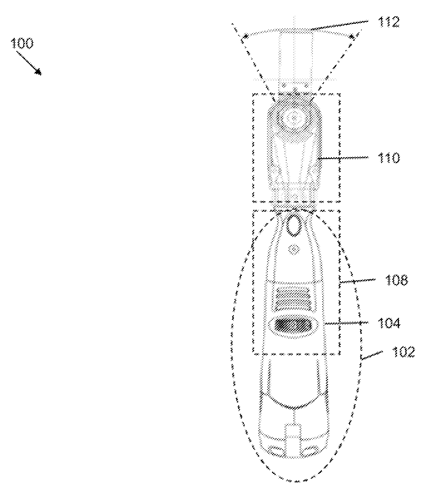
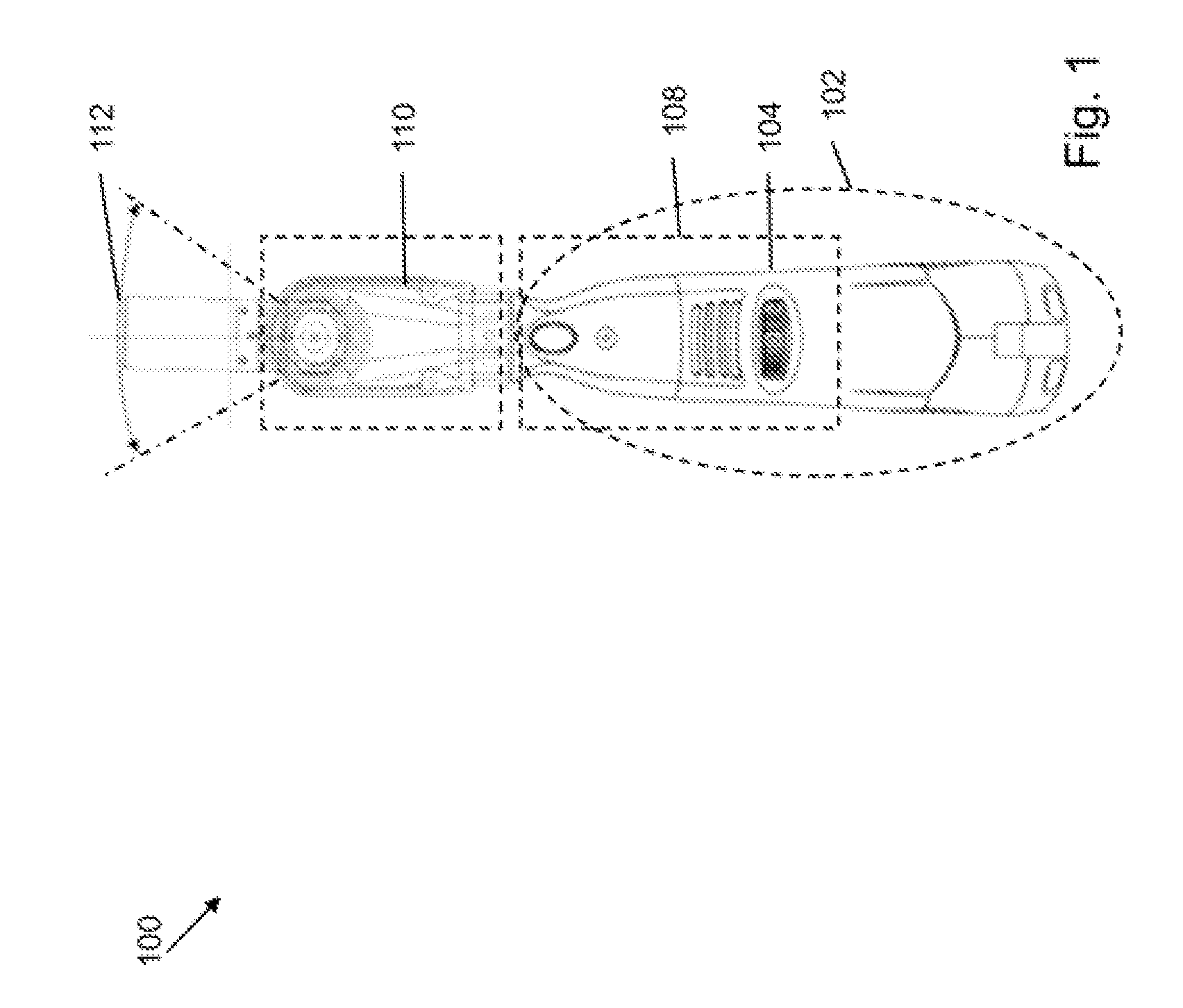
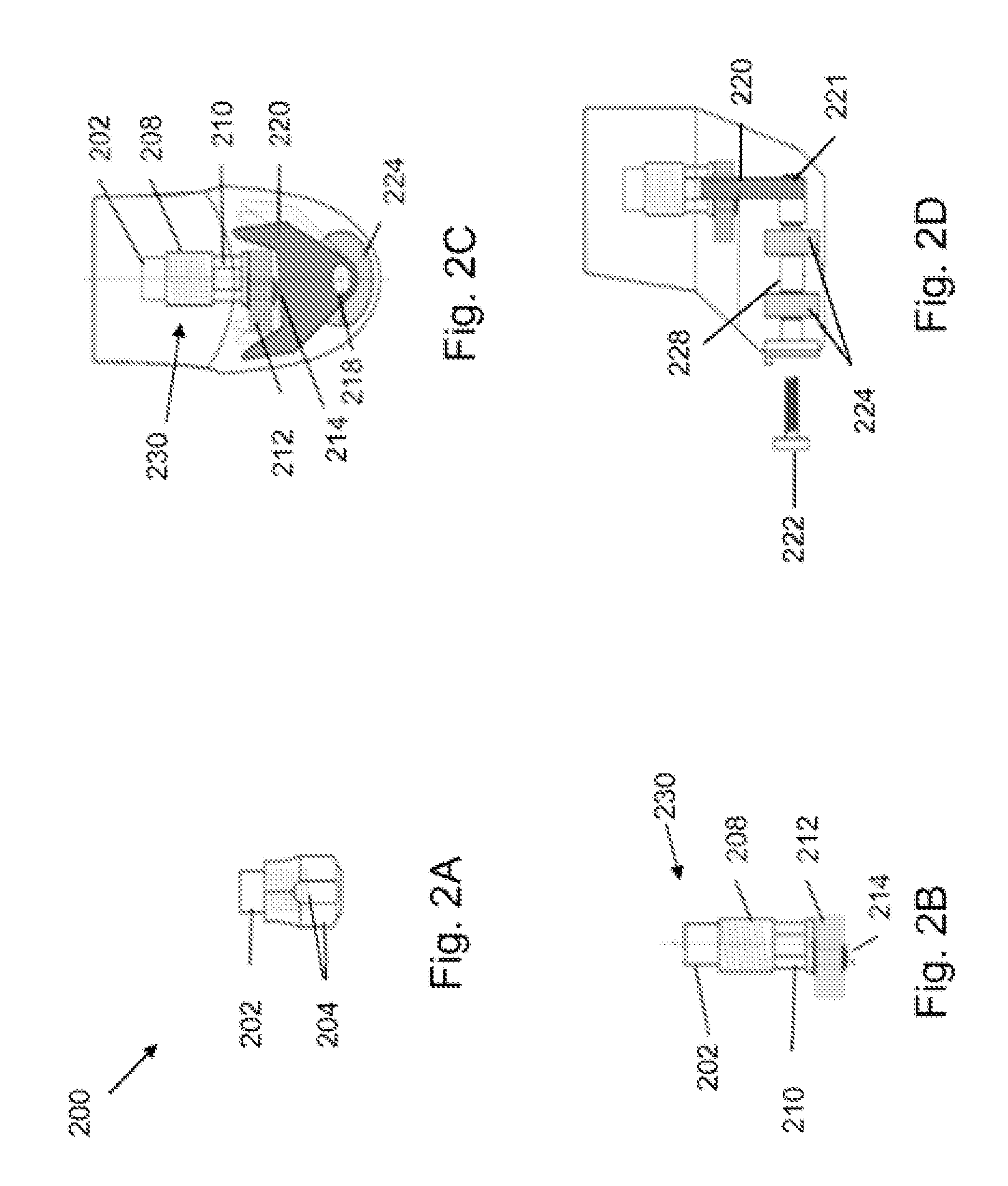
[0011]In embodiments, various additional elements may be added to the attachment facility, such that in operation the rotation of the shaft of the rotary tool creates side-to-side, oscillating movement at high speed. The oscillating attachment may be configured with additional attachment elements to allow various oscillating actions on a work piece, such as sawing, sanding, or the like, with great precision.

Problems solved by technology

This may become a crucial problem or constraint for workmen working in difficult conditions or environments (e.g., high altitude) that restrict the amount of weight and therefore the number of tools that can be carried by the workmen.
In addition, use of separate tools for rotary and oscillating motion may not be economically viable.

Method used


Image

  • Oscillating rotary tool attachment
  • Oscillating rotary tool attachment
  • Oscillating rotary tool attachment

Examples


Embodiment Construction

[0028]While the specification concludes with the claims defining the features of the invention that are regarded as novel, it is believed that the invention will be better understood from a consideration of the following descriptions in conjunction with the drawings / figures, in which like reference numerals are carried forward.

[0029]As required, detailed embodiments of the present invention are disclosed herein; however, it is to be understood that the disclosed embodiments are merely exemplary of the invention, which can be embodied in various forms. Therefore, specific structural and functional details disclosed herein are not to be interpreted as limiting, but merely as a basis for the claims and as a representative basis for teaching one skilled in the art to variously employ the present invention in virtually any appropriately detailed structure. Further, the terms and phrases used herein are not intended to be limiting but rather to provide an understandable description of the...


PUM

PropertyMeasurementUnit
weightaaaaaaaaaa
speedaaaaaaaaaa
detailed structureaaaaaaaaaa

Abstract

The present invention provides an attachment facility for converting a rotary tool to oscillatory tool. The attachment facility may attach to a rotating drive shaft of the rotary tool and may convert the rotating motion of the drive shaft to an oscillating motion. This oscillating motion may provide oscillatory or vibration movements to the blades attached to rotary tool.

Description

CROSS-REFERENCE TO RELATED APPLICATIONS[0001]This application claims the benefit of U.S. provisional application 61 / 048,417 filed on Apr. 28, 2008 which is hereby incorporated by reference in its entirety.BACKGROUND[0002]1. Field[0003]The invention herein disclosed generally relates to rotary tools, and specifically to attachments for converting the rotary motion of the rotary tools to an oscillatory motion.[0004]2. Description of the Related Art[0005]Power tools such as rotary tools and oscillatory tools are used for various machining applications such as cutting, carving, drilling, sanding, polishing, and some other applications. Various types of rotary tools such as rotating drills are manufactured by tool providers and manufacturers. Examples of some known tools include the Dremel 300-N / 35 300 Series tool kit, the Dremel 1100-01 Stylus Cordless Rotary Tool, the Dremel 1130-01, the Dremel Duo 2-tool kit, and some others. Rotary tools typically have attachments, such as drill bits...

Claims


Application Information

Patent Timeline
Patent Type & Authority Applications(United States)
IPC IPC(8): F16H25/16
CPCB23D51/10Y10T74/18056B27B19/006
Inventor KILDEVAELD, MICHAEL ROGLER
Owner KILDEVAELD MICHAEL ROGLER
Learn More