
Interstitially Insulated Pipes and Connection Technologies

a technology of interstitially insulated pipes and connection technologies, which is applied in the direction of pipes, water mains, service pipes, etc., can solve the problems of time-consuming and labor-intensive use of pigs, increasing the difficulty of transporting well products, and increasing the complexity of well products

Inactive Publication Date: 2009-12-31
TEXAS A&M UNIVERSITY
View PDF0 Cites 21 Cited by
  • Summary
  • Abstract
  • Description
  • Claims
  • Application Information

AI Technical Summary

Benefits of technology

The patent describes an interstitially insulated pipeline for flowing hydrocarbon that includes two pipes with an insulating interstice between them containing a layer of screen mesh. The pipeline also includes a joint for connecting the two pipes. The technical effects of this invention include improved insulation, reduced pressure drop, and reduced risk of blockages. Additionally, the patent describes a method for fabricating and transporting hydrocarbon fluid through the pipeline. The invention also includes a subsea pipeline with a rigid inner pipe and a rigid outer pipe, and a layer of screen mesh between them. Overall, the patent aims to address shortcomings of previous devices and provide improved performance of subsea pipelines.

Problems solved by technology

As drilling and production activities advance to greater subsea depths, the challenges and complexities associated with transporting the well products (e.g., produced hydrocarbons) become more challenging.
he buildup of paraffins on the inside of the production pipes and / or subsea pipeline may ultimately lead to narrowing and blockage of the pipeline. A
However, the use of pigs is a reactive method to deal with paraffin wax buildup, and further, the use of pigs takes time, money, and must be periodically repeated to address paraffin wax build-up.
However, such coatings may wear off or degrade over time, especially when there is physical contact and relative motion between the coating and the fluid (e.g., crude oil) flowing through the pipeline.
For instance, the produced crude oil may contain sand or other abrasive elements that wear away the coating over time.
As another example, the corrosive nature of produced crude oil may break down the coating over time.
The wearing away and / or degradation of such a coating tends to reduce its insulating effectiveness, potentially leading to paraffin wax buildup issues.
However, it may not be practical or economically feasible to obtain the desired insulating capabilities (e.g., thermal resistance, thermal performance, etc.) with such techniques.
Further, multiple layers of insulating material(s) may complicate the handling, manipulation, and installation of such insulating materials.
For example, conventional layers of foam insulation provided on the outside of a pipe may crack or become damaged under bending or impact loads experienced during transport, handling, and / or installation.
Damage to the insulating material may reduce its effectiveness and useful life.
As another example, in cases where the desired thermal performance dictates relatively thick layers of insulation (e.g., thick layers of foam insulation necessary to insulate deepwater oil pipelines), the shear size and thickness of such pipes can present transportation and handling challenges.
Still further, some multi-layered insulating materials may present manufacturing complexities.

Method used

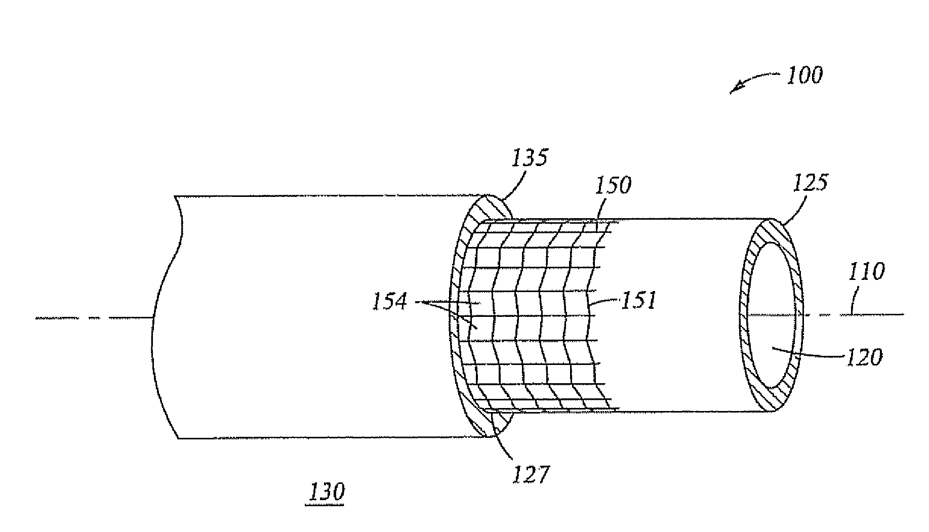
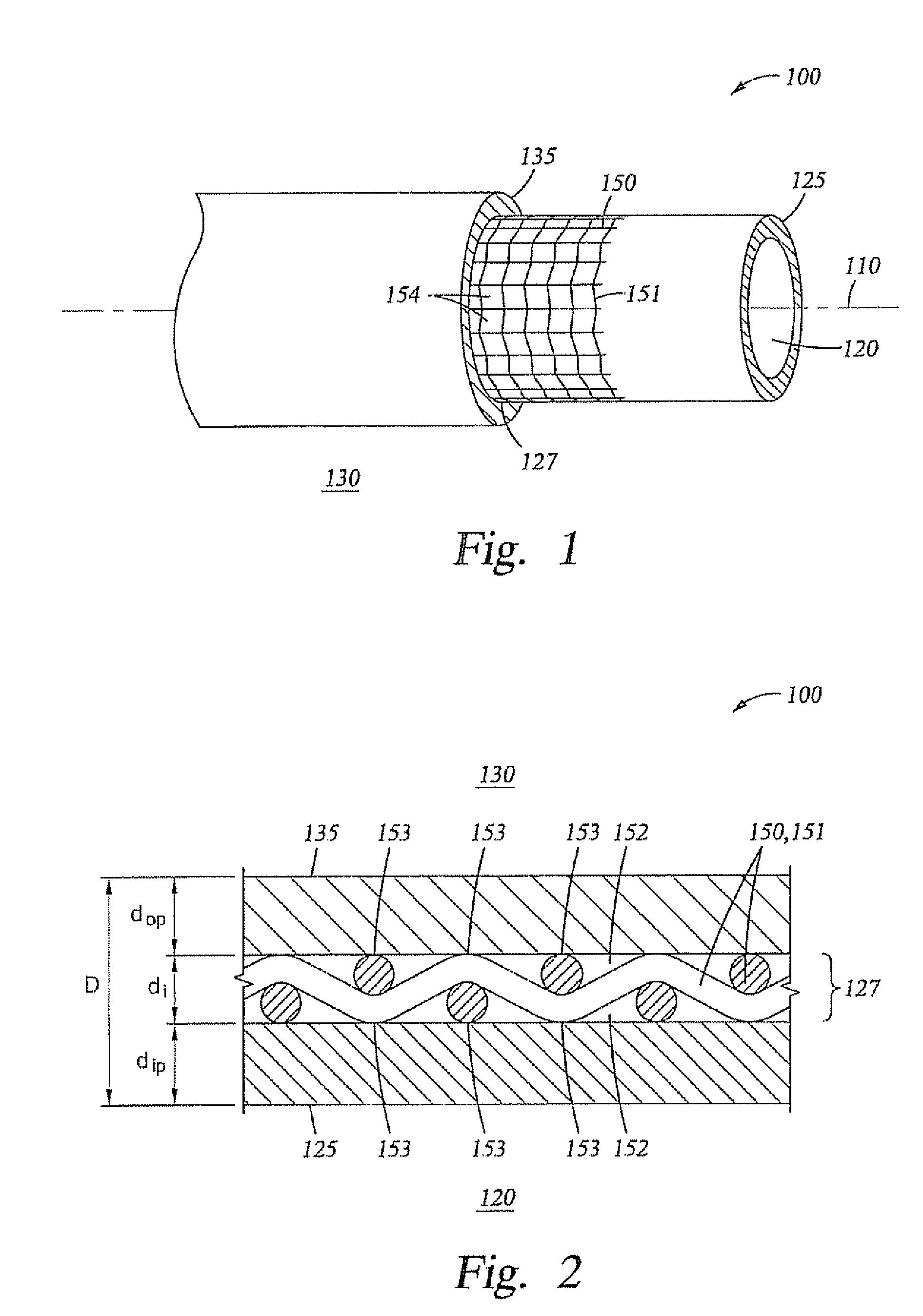

Image

  • Interstitially Insulated Pipes and Connection Technologies
  • Interstitially Insulated Pipes and Connection Technologies
  • Interstitially Insulated Pipes and Connection Technologies

Examples


example 1

[0104]To quantify the thermal resistance and insulting capabilities of a variety of screen meshes, controlled experiments were conducted. The experimental conditions were appropriate for simulating deepwater pipeline applications. Steel slugs made of the same material as subsea pipes (“X-60 or X-80” pipe or low alloy steel AISI 4130 or API Spec 5cT-P110) were used to represent the subsea pipe walls.

[0105]As illustrated in FIG. 12, each test specimen 940 comprised two flux meters 800 and a screen mesh 151 positioned between the flux meters 800. The flux meters 800 were fabricated from the steel slugs previously described. Each flux meter 800 had a length of about 1.5 in.˜(3.81 cm). Five equally spaced holes 801 were drilled to the center of each steel flux meter 800 in order to affix “T” type thermocouples (not shown). The thermocouples measured the temperature in the flux meter 800 at various distances from screen mesh 151 during testing. Cutouts of screen mesh 151 having a diameter...

example 2

[0116]To quantify the thermal performance of an interstitially insulated tubular, controlled experiments were conducted. The experimental facility was appropriate for simulating deepwater applications.

[0117]Stainless steel 5 mesh, the best screen mesh specimen as experimentally determined in EXAMPLE 1, was tested in an assembly similar to a manufactured pipe. The stainless steel 5 mesh was tested between two samples of P110 4140 steel (same material as subsea pipes). The total thickness of this composite pipe wall was 19 mm (0.75 in). Also, a sample of P110 4140 steel, 19 mm (0.75 in) in thickness, without the screen mesh was tested to compare how the screen mesh affected the overall heat transfer coefficient (hj).

[0118]The TCC system 900 illustrated in FIG. 14 and described above was used to conduct the test runs. The experimental study encompassed the range of interface pressures and temperatures typically experienced by subsea pipelines during normal operations. Also, in certain ...

example 3

[0121]To quantify the thermal performance of an interstitially insulated coaxial pipe, controlled experiments were conducted. The experimental facility was appropriate for simulating deepwater applications. Steel slugs made of the same material as subsea pipes (“X-60 or X-80” pipe or medium-carbon steel P110 4140) were used to represent the subsea pipe walls.

[0122]Referring to FIG. 18, each test specimen 940 comprised two flux meters 800, two inserts 402 between the two flux meters 800, and a separator 150 (e.g., screen mesh) positioned between the two inserts 402. The flux meters 800 were fabricated from the steel slugs. Each flux meter 800 had a length of about 3.81 cm (1.5 in.). Five equally spaced holes 801 were drilled to the center of each steel flux meter 800 in order to affix “T” type thermocouples (not shown). The thermocouples measured the axial temperature distributions in the flux meter 800 during testing. The inserts 402 were machined from P110 4140 steel bar stock into...


PUM

PropertyMeasurementUnit
heat transfer coefficientaaaaaaaaaa

Abstract

An interstitially insulated pipeline for flowing a hydrocarbon. In an embodiment, the pipeline comprises a first interstitially insulated pipe and a second interstitially insulated pipe. Each interstitially insulated pipe comprises an inner pipe, an outer pipe mounted coaxially around the inner pipe, an insulating interstice radially positioned between the inner pipe and the outer pipe, and a layer of screen mesh having a mesh size 10 or less disposed in the insulating interstice. In addition, the pipeline comprises a joint coupling the first interstitially insulated tubular and the second interstitially insulated tubular end-to-end. The joint includes a connection that couples the outer pipe of the first interstitially insulated pipe to the outer pipe of the second interstitially insulated pipe, and an annular seal member disposed between the inner pipe of the first interstitially insulated pipe and the inner pipe of the second interstitially insulated pipe.

Description

CROSS-REFERENCE TO RELATED APPLICATIONS[0001]This application is a continuation in part of U.S. application Ser. No. 11 / 339,644, filed Jan. 25, 2006, and entitled “Interstitial Insulation,” which claims the benefit of U.S. Provisional Application No. 60 / 646,765, filed Jan. 25, 2005, and entitled “Interstitial Insulation,” each of which is hereby incorporated herein by reference in its entirety. In addition, this non-provisional application claims the benefit of U.S. Provisional Application No. 60 / 746,110, filed May 1, 2006, and entitled “Interstitially Insulated Tubulars and Connection Technologies for Interstitially Insulated Tubulars,” which is hereby incorporated by reference in its entirety.STATEMENT REGARDING FEDERALLY SPONSORED RESEARCH OR DEVELOPMENT[0002]This invention was made with Government support under research contracts from the Marine Mineral Service (MMS) (MMS Project #509) under Contract No. 0104RU35515. The government may have certain rights in this invention.BACKG...

Claims


Application Information

Patent Timeline
Patent Type & Authority Applications(United States)
IPC IPC(8): F16L9/14F16L9/18B23P17/00F17D1/00
CPCB32B1/08B32B3/08B32B5/02E04B1/78Y10T29/49428F16L59/07F16L59/12F16L59/143E04B2001/7691B32B5/022B32B5/024B32B15/043B32B15/18B32B3/266B32B2255/06B32B2255/26B32B2307/304B32B2307/714B32B2597/00Y10T137/0318Y10T137/9029Y10T137/402
Inventor FLETCHER, LEROY S.MAROTTA, EGIDIO E.BOLLFRASS, CHARLES A.
Owner TEXAS A&M UNIVERSITY
Learn More