Home kitchen fire suppression system

a fire suppression system and home kitchen technology, applied in fire rescue and other directions, can solve the problem of deprived fire of additional combustible materials

Inactive Publication Date: 2009-12-31
LALOUZ SHLOMO
View PDF3 Cites 21 Cited by
  • Summary
  • Abstract
  • Description
  • Claims
  • Application Information

AI Technical Summary

Problems solved by technology

Furthermore, the system immediately disconnects the external source of energy, whether gas or electricity, consumed by the cooking appliance thus depriving the fire of additional combustible material.

Method used


Image

  • Home kitchen fire suppression system
  • Home kitchen fire suppression system
  • Home kitchen fire suppression system

Examples


Embodiment Construction

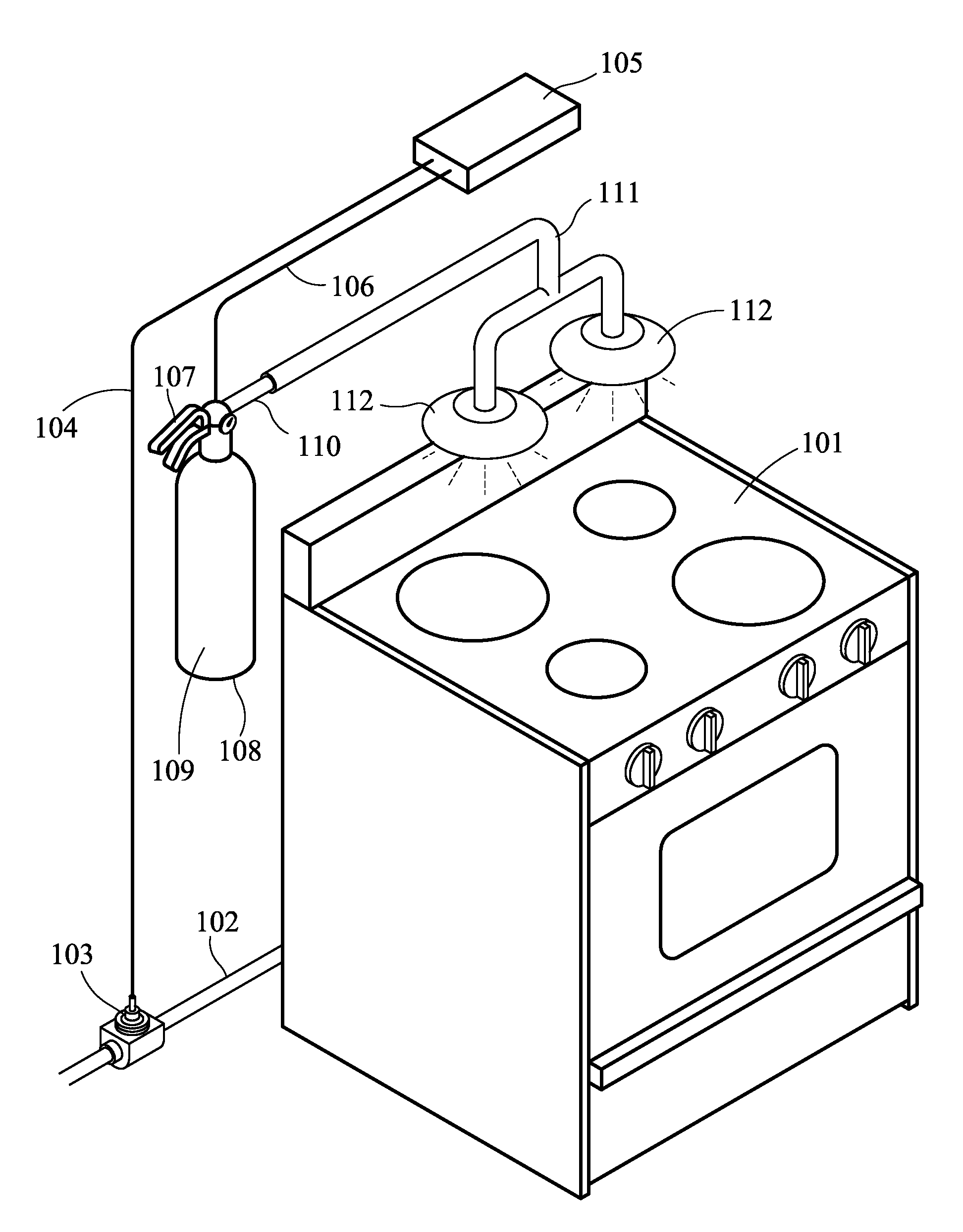
[0013]FIG. 1a depicts a preferred embodiment of the invention. A cooking appliance 101 may be operated by gas burner through an externally supplied flammable gas, such as natural gas or liquid propane gas, by an electrically operated heating element through an externally supplied electricity, by an appliance adjacent flammable gas container, such as liquid propane gas or butane gas, or by any flammable material such as coal or wood.

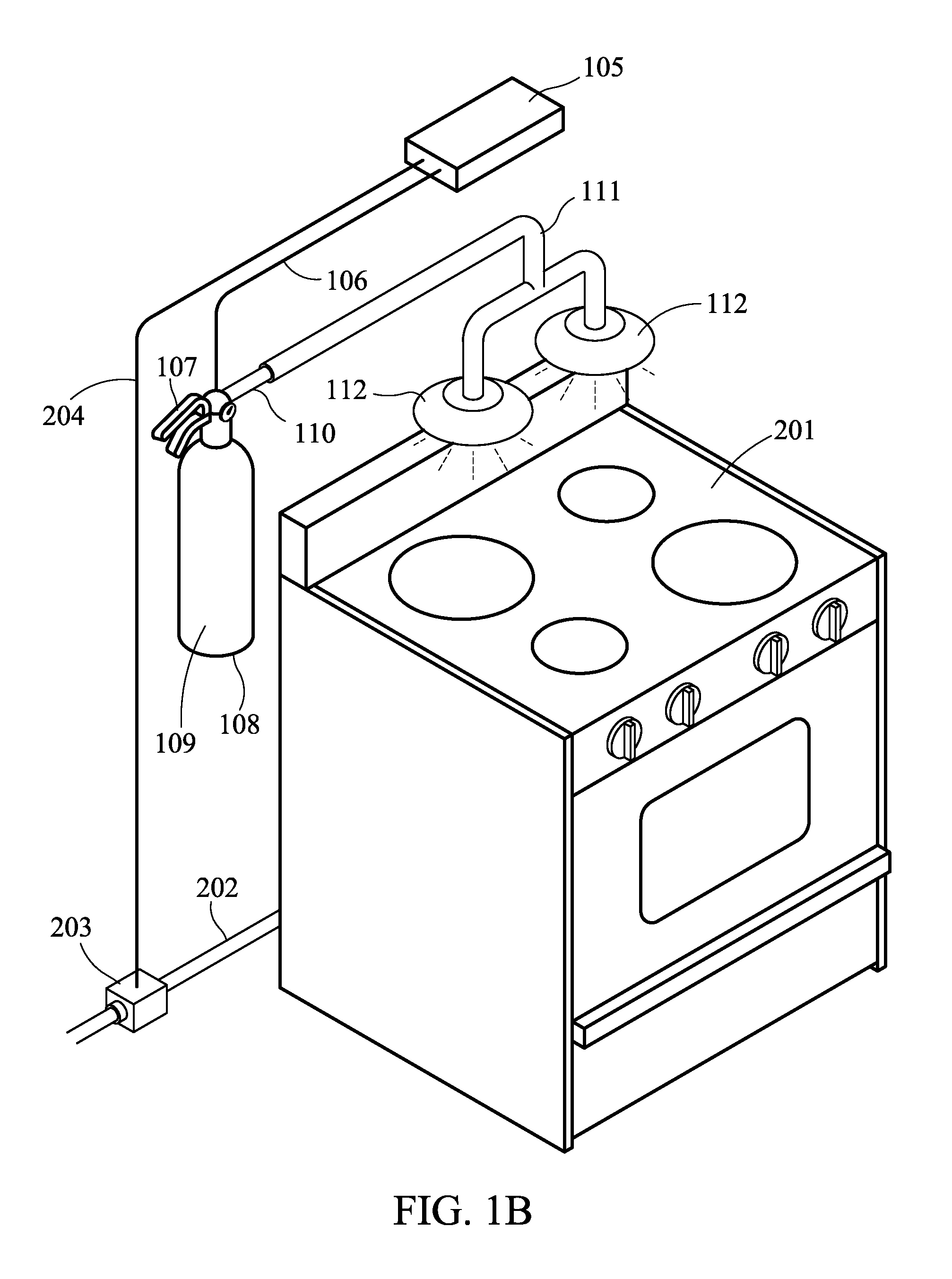
[0014]In most modern and urban kitchens the energy consumed by a cooking appliance is supplied through external supply line, such as a gas supply line 102 or and electricity supply line 202 (See FIG. 1b).

[0015]In the event the cooking appliance is gas operated, most building codes mandate that an external gas shut-off valve be adjacent to the appliance, however this gas shut-off valve is normally not easily accessible in the event of a fire, lending more consumable energy to an uncontrollable fire.

[0016]The inventive home kitchen fire suppression system e...


PUM


Abstract

An automatic fire-suppression system that upon a predetermined fire condition is capable of detecting said fire condition and automatically dispensing and dispersing fire suppressant material over the abnormal fire.
The system is independent of the appliance and does not require any external energy to operate. Furthermore the fire suppression system is capable of disconnecting an external gas or electricity supply line upon a fire condition.

Description

BACKGROUND OF THE INVENTION[0001]1. Field of the Invention[0002]This invention generally relates to a system to suppress dangerous fires caused by or on cooking appliances. More particularly, this invention relates to a self contained system that can detect a cooking appliance fire condition, such as a prolonged and abnormal kitchen stove top flame or excessive heat emanating from a cooking appliance, and, upon the triggering of a fusible link or other detection means, douse off the abnormal fire with a fire suppressant material while simultaneously disconnecting the cooking appliance supply lines. The fire suppressing system is self contained and powered and requires the same maintenance as a standard fire suppressant canister.[0003]2. Description of Related Prior Art[0004]Since humans started to cook indoors with combustible materials, fuels, or electricity, the risk of fire caused by an accident or failure of the cooking device, became part of daily human life. An uncontrolled an...

Claims


Application Information

Patent Timeline
Patent Type & Authority Applications(United States)
IPC IPC(8): A62C37/12A62C3/00
CPCA62C37/12A62C3/006
Inventor LALOUZ, SHLOMO
Owner LALOUZ SHLOMO
Why Eureka
Try Eureka