Water-dispensing appliance and drinks-dispensing arrangement with a water-dispensing appliance

a technology for water dispensers and water dispensers, applied in the direction of liquid transfer devices, liquid/fluent solid measurement, packaging, etc., can solve the problems of high energy consumption, high water consumption, and risk of water contamination in the appliance, and achieve the effect of inhibiting bacterial growth and good

Inactive Publication Date: 2009-12-31
ALFRED KARCHER GMBH & CO KG
View PDF13 Cites 46 Cited by
  • Summary
  • Abstract
  • Description
  • Claims
  • Application Information

AI Technical Summary

Benefits of technology

[0010]It is advantageous if the main line has a feed portion, which connects the water heater to the water inlet, and a dispensing portion, which connects the water heater to the dispensing device, and if the start of the return line is line-connected to the dispensing portion and the end of the return line is line-connected to the feed portion. In this embodiment, the water heater is incorporated in the main line. The water heater can thus be used both for dispensing hot water during normal operation and for heating up the water for a thermal sterilizing operation. Furthermore, this makes it possible for the feed portion to be thermally sterilized between its region which is line-connected to the end of the return line and the water heater.
[0035]It is advantageous if the water-dispensing appliance has an automatic cleaning device. For example, it is possible to provide a tablet magazine which contains descaling tablets, and the control device can cause the latter to be dispensed. Such a cleaning operation can be carried out, for example, following a thermal sterilizing operation.

Problems solved by technology

Common to all variants is the problem of dispensing water to a consumer in as germ-free a manner as possible.
In addition, there is a risk of contamination of water stored in the appliance.
The hot water is then discarded, so that the sterilizing operation involves high energy and high water consumption.

Method used


Image

  • Water-dispensing appliance and drinks-dispensing arrangement with a water-dispensing appliance
  • Water-dispensing appliance and drinks-dispensing arrangement with a water-dispensing appliance
  • Water-dispensing appliance and drinks-dispensing arrangement with a water-dispensing appliance

Examples


first embodiment

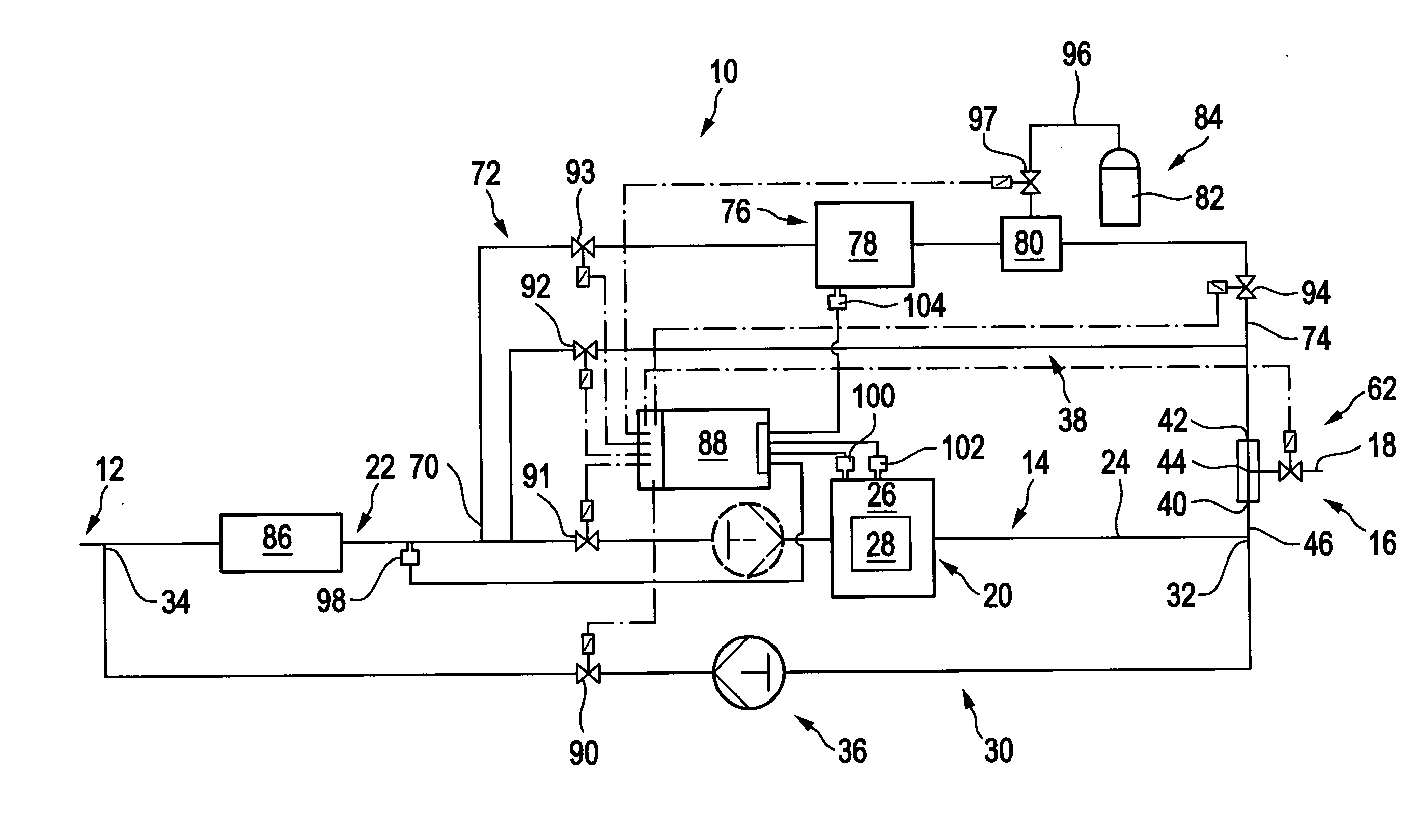
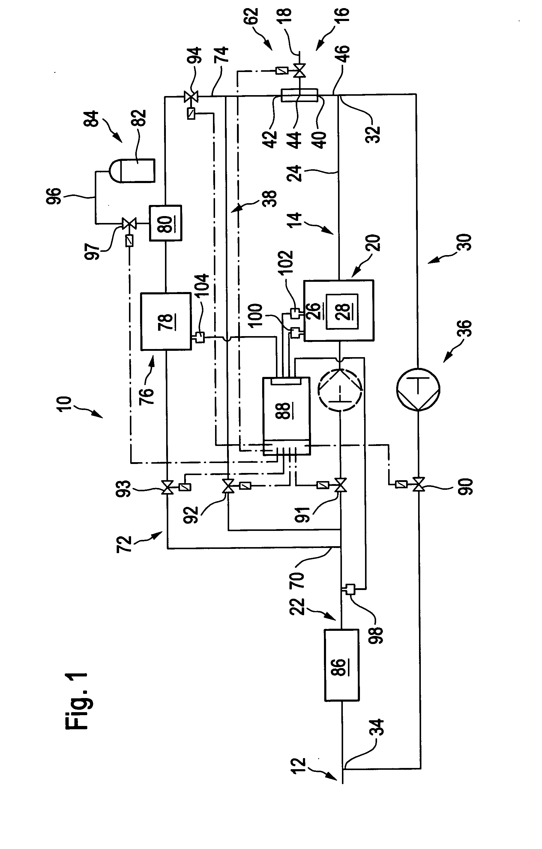
[0043]the water-dispensing appliance according to the invention is illustrated schematically in FIG. 1 and designated as a whole there by the reference numeral 10. The water-dispensing appliance 10 is in the form of a so-called water dispenser, which is set up, for example, in public buildings, hospitals or stores, hotels, etc. and is designed for dispensing preferably predetermined quantities of drinking water.

[0044]Via a water inlet 12, the water-dispensing appliance 10 can be connected to a water-supply means, preferably the public water-supply network. The water inlet 12 is connected, via a main line 14, to a dispensing device 16 which has a water outlet 18, via which the water which a user requires can be dispensed to him.

[0045]The main line 14 has incorporated in it a water heater 20 which is connected to the water inlet 12 via a feed portion 22, which forms an upstream portion of the main line 14. The water heater 20 is connected to the dispensing device 16 via a dispensing p...

second embodiment

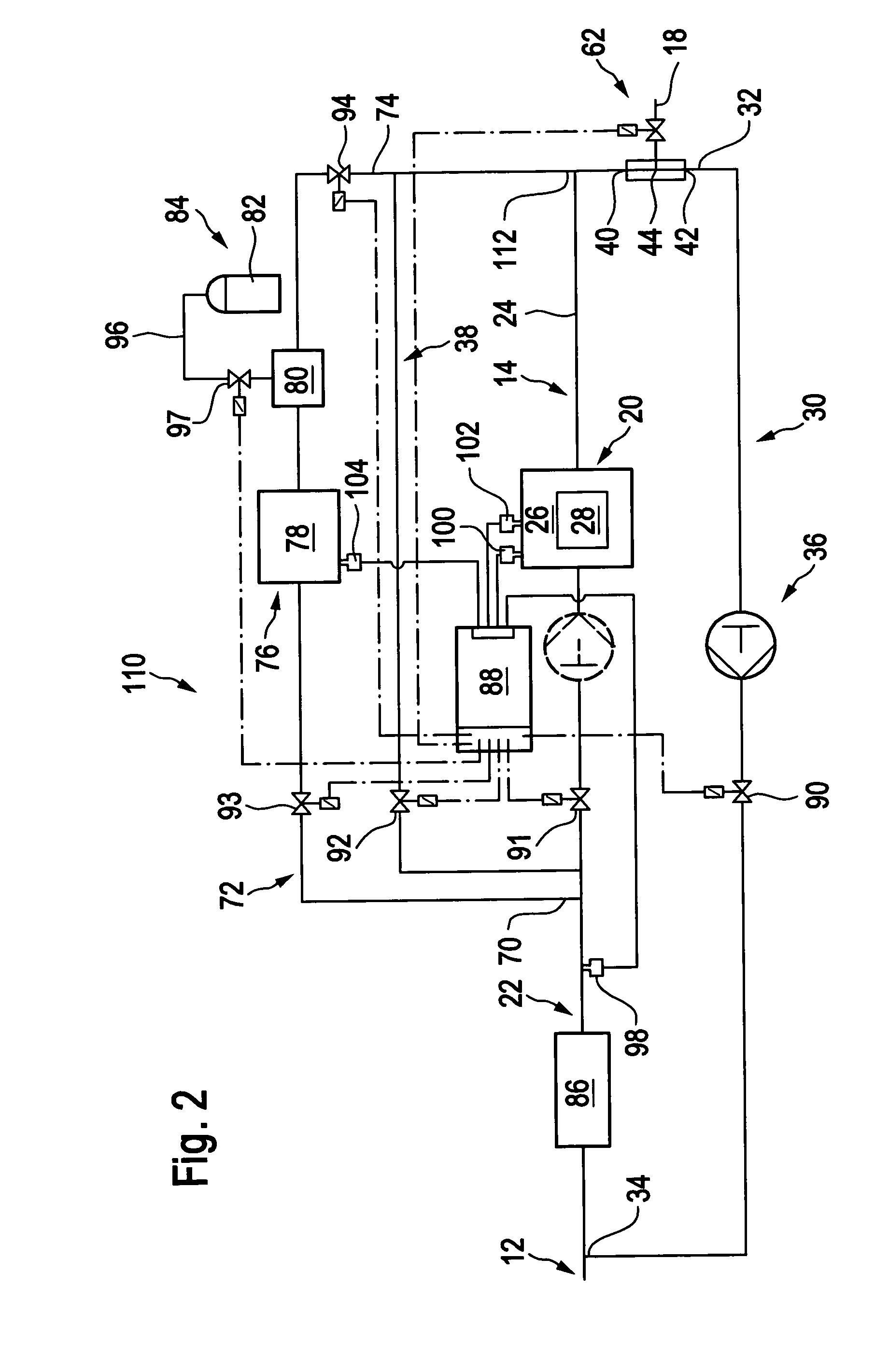
[0064]the water-dispensing appliance according to the invention is shown in FIG. 2 and designated there by the reference numeral 110. The water-dispensing appliance 10 differs from the water-dispensing appliance 10 in the way in which the dispensing device 16 is connected to the main line 14, the return line 30 and the bypass line 38.

[0065]In the water-dispensing appliance 110, the return-line start 32 is connected to the second connection 42 of the dispensing device 16 and, in this way, is line-connected to the dispensing portion 24 of the main line 14. The bypass line 38 is connected to the main line 14 by virtue of its end 112 being branched into the dispensing portion 24 in the vicinity of the first connection 40. The water-dispensing appliance 110 likewise has the features and advantages already described in conjunction with the water-dispensing appliance 10.

[0066]The water-channeling components of the water-dispensing appliances 10 and 110 may be provided, at least in part, wi...


PUM

PropertyMeasurementUnit
temperatureaaaaaaaaaa
timeaaaaaaaaaa

Abstract

A water-dispensing appliance is provided, in particular for dispensing drinking water, comprising a water inlet which can be connected to a water-supply device, also comprising a dispensing device with a water outlet, via which water can be dispensed from the appliance, the dispensing device being connected to the water inlet via a main line which has a downstream portion and an upstream portion, and also comprising a water heater. The water-dispensing appliance has a return line, of which the start is line-connected to the downstream portion of the main line and the end is connected to the upstream portion of the main line, and the appliance also has a delivery unit in order for water heated up by means of the water heater to be delivered through the main line from the upstream portion to the downstream portion.

Description

[0001]This application is a continuation of international application No. PCT / EP2007 / 009821 filed on Nov. 14, 2007.[0002]The present disclosure relates to the subject matter disclosed in international application number PCT / EP2007 / 009821 of Nov. 14, 2007 and German application number 10 2006 062 352.5 of Dec. 22, 2006, which are incorporated herein by reference in their entirety and for all purposes.BACKGROUND OF THE INVENTION[0003]The invention relates to a water-dispensing appliance, in particular for dispensing drinking water, comprising a water inlet which is adapted to be connected to a water-supply device, also comprising a dispensing device with a water outlet, via which water can be dispensed from the appliance, the dispensing device being connected to the water inlet via a main line which has a downstream portion and an upstream portion, and also comprising a water heater.[0004]The invention also relates to a drinks-dispensing arrangement with a water-dispensing appliance.[...

Claims


Application Information

Patent Timeline
Patent Type & Authority Applications(United States)
IPC IPC(8): C02F1/02B67D1/08B67D5/62B67D5/56B67D7/74B67D7/80
CPCC02F1/02C02F1/444C02F9/005C02F2303/04F24D19/1051F16K31/0624F24D17/0073F24D17/0078F16K11/04C02F9/20
Inventor SIEMER, ANDREASMAIER, NORBERT
Owner ALFRED KARCHER GMBH & CO KG
Why Eureka
Try Eureka