Space based orbital kinetic energy weapon system

a kinetic energy and space technology, applied in the field of space-based weapon systems, can solve the problems of reaching the limit regarding the time it takes, affecting the safety of space exploration, and causing undesirable ramifications

Active Publication Date: 2009-12-31
SCAPA FLOW
View PDF10 Cites 18 Cited by
  • Summary
  • Abstract
  • Description
  • Claims
  • Application Information

AI Technical Summary

Benefits of technology

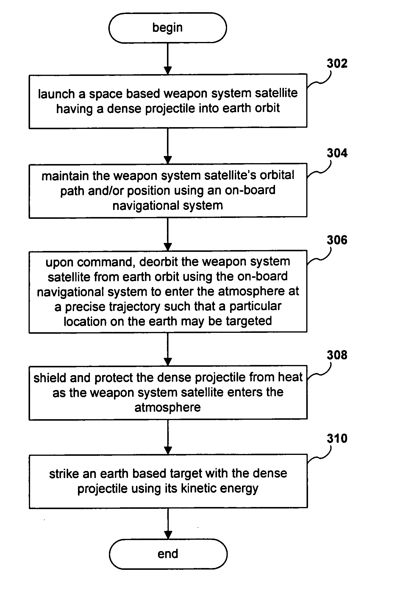
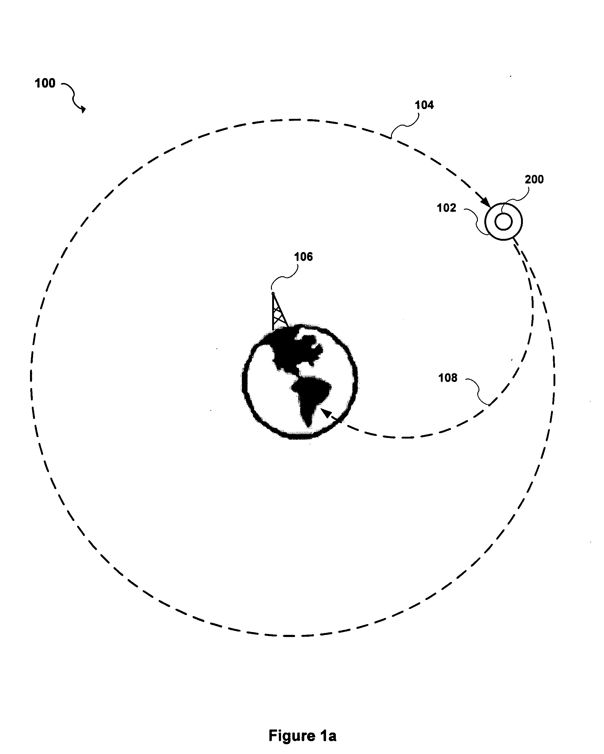
[0009]Accordingly, one aspect of the present invention is to provide a space based orbital kinetic energy weapon system that includes a satellite having a control system configured to maintain an orbit in outer space around the earth and to deorbit the satellite on a desired trajectory corresponding to an earth based target upon a command, and a projectile object operably connected to the satellite. The projectile object includes a dense mass and a heat shield operably surrounding the mass such that at least a portion of the mass survives reentry into the earth's atmosphere and strikes the earth based target delivering its kinetic energy.
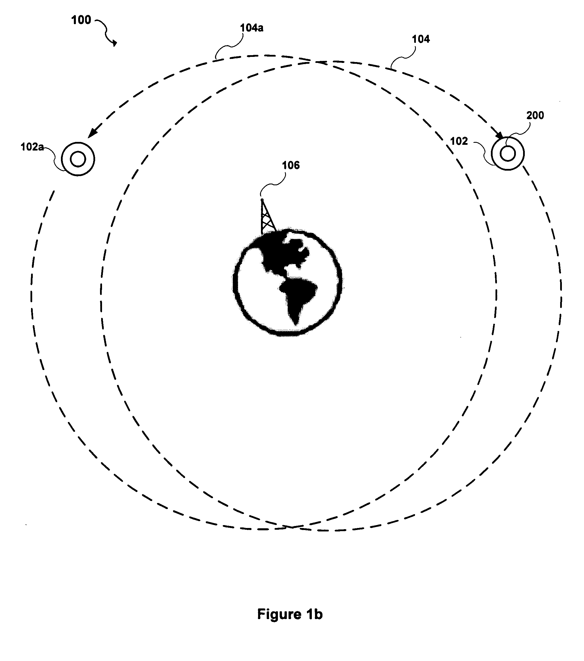
[0010]Another aspect of the present invention is to provide a space based orbital kinetic energy weapon system that includes a plurality of satellites and a plurality of projectile objects. Each satellite includes a control system configured to maintain an orbit in outer space around the earth and to deorbit the satellite on a desired trajectory corresponding to an earth based target upon a command. Each projectile object includes a dense mass and a heat shield operably surrounding the mass such that a substantial portion of the mass survives reentry into the earth's atmosphere and strikes the earth based target delivering its kinetic energy. Each projectile object is operably connected to a corresponding one of the satellites.
[0011]Yet another aspect of the present invention is to provide a space based orbital kinetic energy weapon system that includes a satellite having an orbit in outer space around the earth and a plurality of projectile objects. Each projectile object is detachably connected to a corresponding one of the satellites. Each projectile object includes a dense mass, a heat shield operably surrounding the mass, and a control system configured to deorbit the payload on a desired trajectory corresponding to an earth based target upon command. The heat shield is configured to survive reentry into the earth's atmosphere. Each projectile object is configured to strike the earth based target delivering its kinetic energy.
[0012]Another aspect of the present invention is to provide a method for implementing an orbital kinetic energy weapon system that includes launching a plurality of satellites into earth orbits, maintaining an orbital path for each of the satellites, upon command, deorbiting at least one satellite on a desired trajectory, and striking one or more earth based locations with one or more projectile objects. Each satellite includes the one more projectile objects and a control system. Each projectile object comprises a dense mass and a heat shield operably surrounding the mass such that a substantial portion of the mass survives reentry into the earth's atmosphere and strikes the earth based target delivering its kinetic energy. The orbital path for each of the satellites is maintained using the respective control systems. The at least one satellite on a desired trajectory is deorbited using the respective control systems.
[0013]Another aspect of the present invention is to provide a method for implementing an orbital kinetic energy weapon system that includes launching a plurality of satellites into earth orbits, maintaining an orbital path for each of the satellites using the respective control systems, and, upon command, deorbiting at least one satellite on a desired trajectory using the respective control systems. Each satellite includes one more projectile objects and a control system, and each projectile object comprises a dense mass. The method further includes heat shielding the mass such that at least a portion of the mass survives reentry into the earth's atmosphere, and striking one or more earth based locations with the projectile objects and delivering a kinetic energy.

Problems solved by technology

Like the artillery before them, however, they also reached their practical limit.
While the ICBM can strike a target anywhere on earth, it has reached its limit regarding the time it takes to engage a selected target.
Other more extreme weapons, such as nuclear warheads have politically undesirable ramifications, and the destructive capability of conventional warheads is not appreciably progressing.
Thus, there exists an unmet need in the art to deliver destructive energy more efficiently and effectively.

Method used


Image

  • Space based orbital kinetic energy weapon system
  • Space based orbital kinetic energy weapon system
  • Space based orbital kinetic energy weapon system

Examples


Embodiment Construction

[0021]Referring now to the drawings, wherein like reference numerals designate identical or corresponding parts throughout the several views, preferred embodiments of the present invention are described.

[0022]Today there exists a new kind of warfare. Information on the battlefield is more quickly processed and targets are more quickly acquired. There exists a need for weapon systems that are more powerful and which can be quickly deployed. The present invention provides a more destructive capability than any previous system and can reach its target in minutes rather than hours. Additionally, the present invention is impervious to any known defense system.

[0023]The present invention provides a space based orbital kinetic energy system that includes one or more weapon system satellites orbiting the earth from space. Kinetic energy is energy of motion. The kinetic energy of an object is the energy it possesses because of its motion. The kinetic energy (KE) of an object may be calculate...


PUM


Abstract

A space based orbital kinetic energy weapon system and method of using same is provided. The space based orbital kinetic energy weapon system includes a satellite having a control system configured to maintain an orbit in outer space around the earth and to deorbit the satellite on a desired trajectory corresponding to an earth based target upon a command, and a projectile object operably connected to the satellite. The projectile object includes a dense mass and a heat shield operably surrounding the mass such that at least a portion of the mass survives reentry into the earth's atmosphere and strikes the earth based target delivering its kinetic energy.

Description

CROSS REFERENCE TO RELATED APPLICATIONS[0001]The present document claims the benefit of the earlier filing date of co-pending U.S. provisional patent application Ser. No. 60 / 683,568, entitled “SPACE BASED ORBITAL KINETIC ENERGY WEAPON SYSTEM,” filed in the U.S. Patent and Trademark Office on May 23, 2005, and having a common inventor as the present document, the entire contents of which is incorporated herein by reference.BACKGROUND OF THE INVENTION[0002]1. Field of the Invention[0003]The present invention relates to space based weapon systems and more particularly, relates to a space based orbital kinetic energy weapon system and related methods for implementing and operating the same.[0004]2. Discussion of the Background[0005]Throughout the history of armed conflict strategic weapons have evolved to become more powerful, more accurate, and more quickly deployed. The catapult gave rise to the cannon from which artillery eventually evolved. The range and caliber of artillery increas...

Claims


Application Information

Patent Timeline
Patent Type & Authority Applications(United States)
IPC IPC(8): B64G1/10
CPCB64G1/1085B64G1/242B64G1/62B64G1/58B64G1/26
Inventor DORMAN, JOHN
Owner SCAPA FLOW
Why Eureka
Try Eureka