Image capture assembly

a technology for capturing and assembling images, applied in the field of image capture devices, can solve problems such as assembly prolongation

Inactive Publication Date: 2009-12-31
HON HAI PRECISION IND CO LTD
View PDF2 Cites 27 Cited by
  • Summary
  • Abstract
  • Description
  • Claims
  • Application Information

AI Technical Summary

Problems solved by technology

This prolon

Method used


Image

  • Image capture assembly
  • Image capture assembly
  • Image capture assembly

Examples


Embodiment Construction

[0011]Embodiments of the present image capture assembly will now be described in detail with references to the drawings.

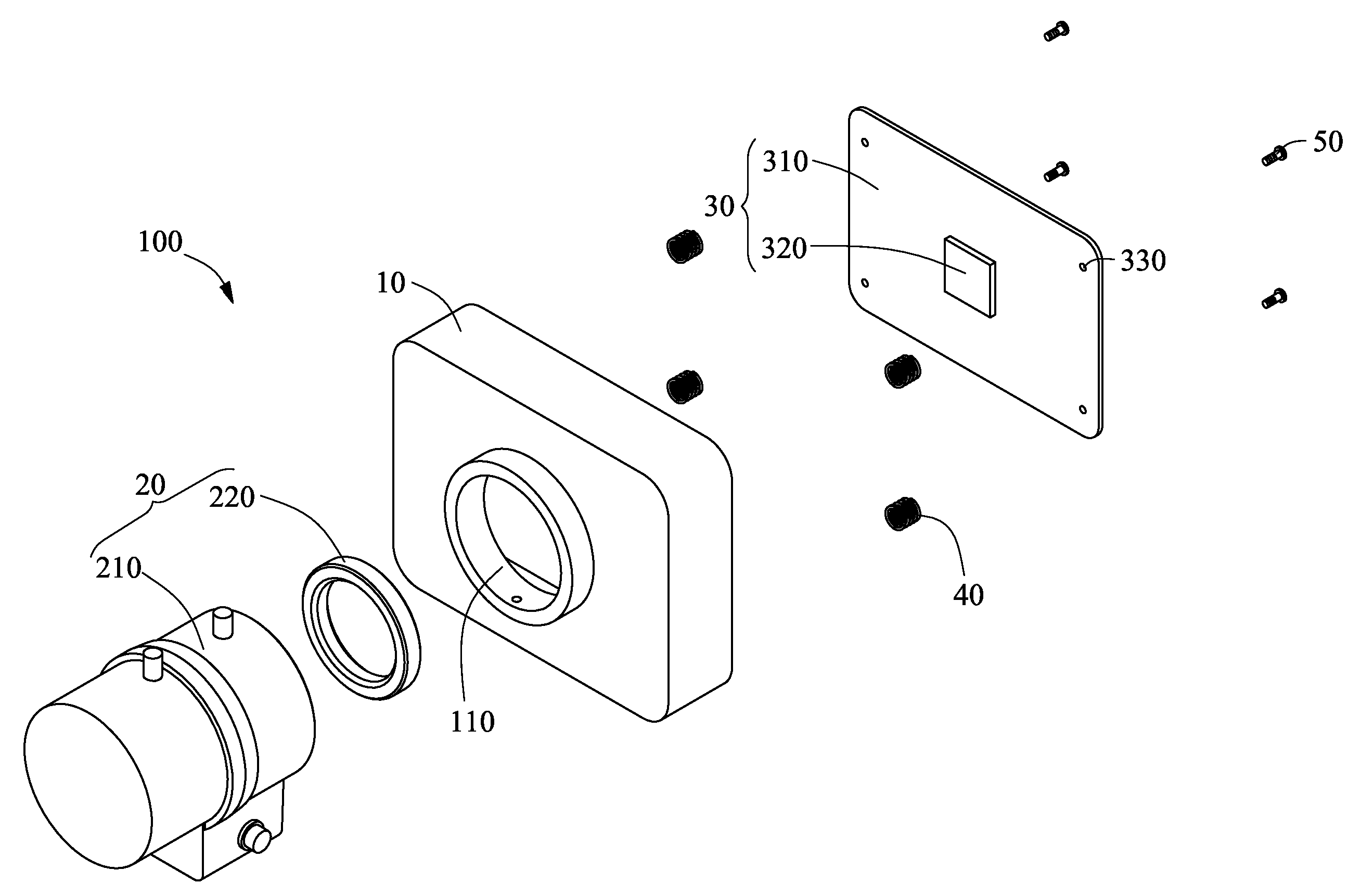
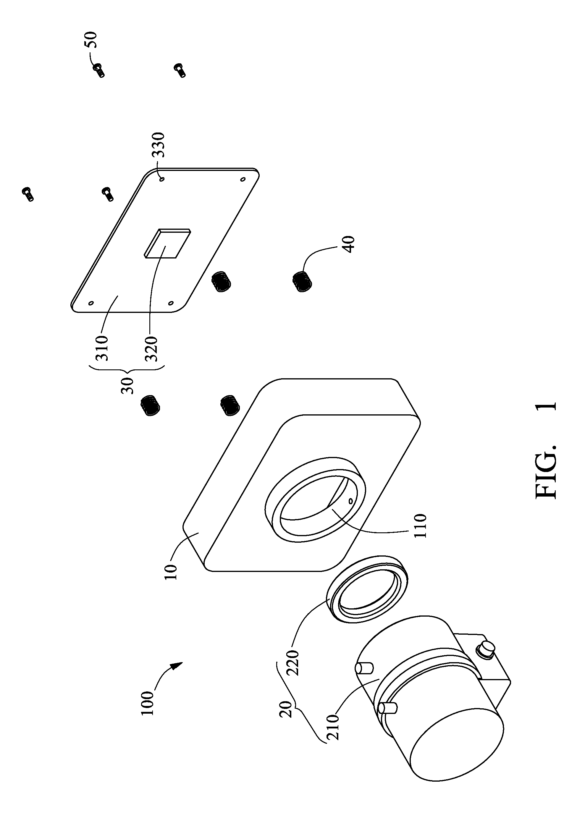
[0012]Referring to FIG. 1 and FIG. 2, an image capture assembly 100 includes a housing 10, a lens unit 20, an image detection unit 30, four screws 50, and four elastic members 40.

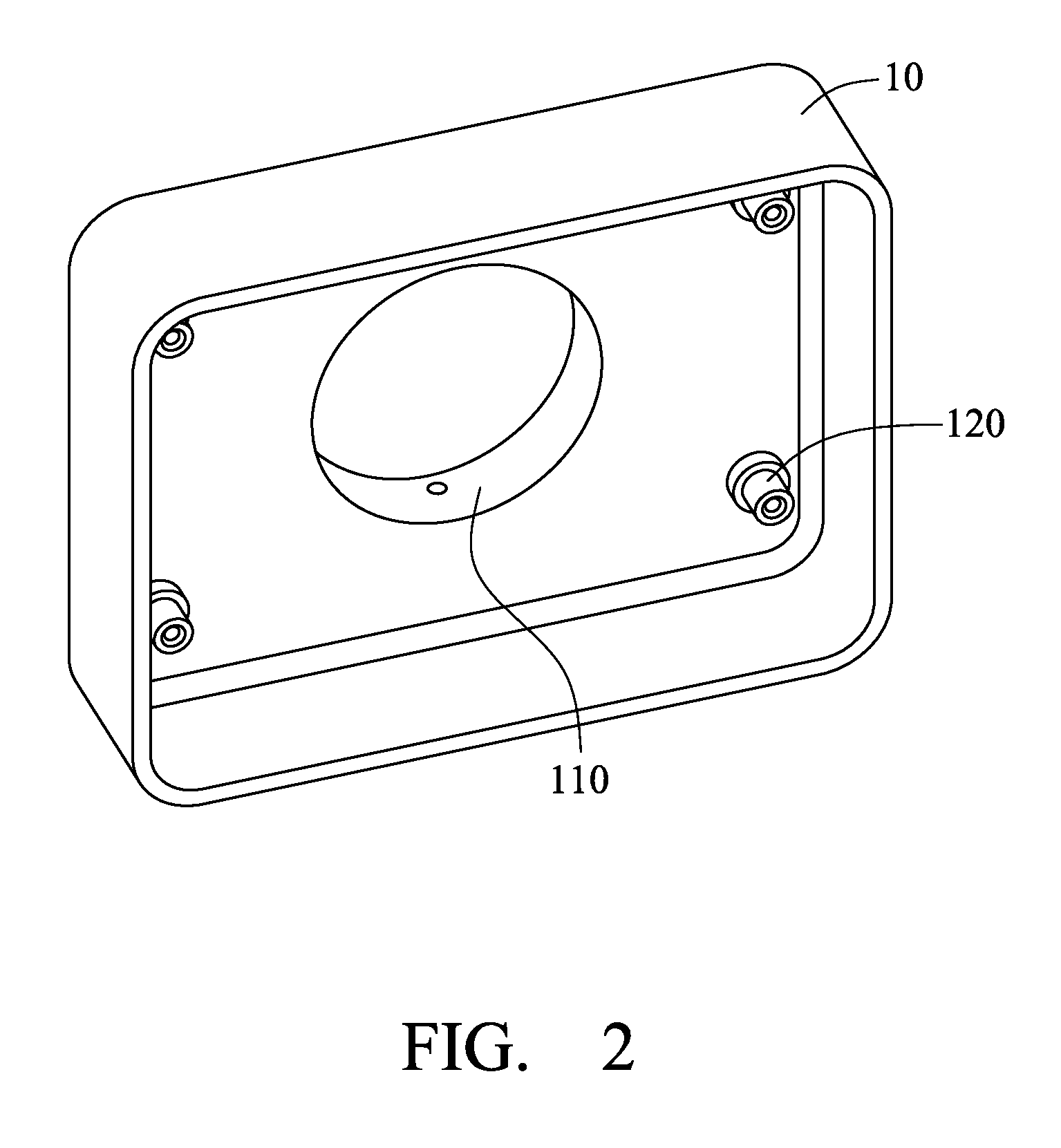
[0013]The housing 10 includes a lens-receiving portion 110 and four screw-receiving portions 120. The lens-receiving portion 110 is a first tube extending outward from the outer surface of the housing 10. The four screw-receiving portions 120 are four second tubes protruding inward from the inner surface of the housing 10 and surrounding the lens-receiving portion 110. One end surface of each of the four screw-receiving portions 120 defines a threaded hole.

[0014]The lens unit 20 includes a lens barrel 210 and a lens ring 220, mounted on the lens-receiving portion 110 of the housing 10. The lens barrel 210 is fixed to the lens ring 220 and includes at least one lens. In this embodiment, the...


PUM


Abstract

An image capture assembly is disclosed. The image capture assembly includes a housing, a lens unit, an image detection unit, three screws, and three elastic members. The housing includes a lens-receiving portion, and three screw-receiving portions on an inner surface of the housing and surrounding the lens-receiving portion, an end surface of each screw-receiving portion defining a threaded hole. The lens unit is received in the lens-receiving portion. The image detection unit includes a substrate and an image sensor. The substrate facing the inner surface of the housing defines three through holes therein aligned with the three screw-receiving portions respectively. The image sensor is fixed to the substrate and faces the lens-receiving portion. The screws extend through the through holes of the substrate and into the threaded holes of the screw-receiving portions respectively. The elastic members surround the screw-receiving portions respectively and are compressed between the housing and the substrate.

Description

BACKGROUND[0001]1. Technical Field[0002]The invention relates to image capture devices and, more particularly, to an image capture assembly moving an image sensor thereof relative to a lens thereof.[0003]2. Description of the Related Art[0004]Usually, image capture devices include a lens and an image sensor. To ensure image quality, an optical axis of the lens must be perpendicular to a light-receiving surface of the image sensor and pass through the central point of the light-receiving surface. In reality, deviations from such requirement are common. Therefore, tests for whether the image capture devices satisfy the requirement and, sometimes, sequential repositioning are required. To eliminate the deviation, washers are employed to reposition the image sensor. When deviation is detected after assembly, the image capture device must be disassembled to interpose the washer(s). This prolongs assembly.[0005]Therefore, it is desirable to provide an image capture assembly, which can ove...

Claims


Application Information

Patent Timeline
IPC IPC(8): G03B17/02G03B17/00H04N5/225
CPCG03B17/02G02B7/026
Inventor WANG, SHAO-HUNG
Owner HON HAI PRECISION IND CO LTD
Why Eureka
Try Eureka