Apparatuses and methods for accurate structure marking and marking-assisted structure locating

a technology of marking and structure, applied in the field of manufacturing products, can solve the problems of less likely to have the benefits of different locations and the only part of state of the art manufacturing equipmen

Active Publication Date: 2017-10-17
THE BOEING CO
View PDF51 Cites 12 Cited by
  • Summary
  • Abstract
  • Description
  • Claims
  • Application Information

AI Technical Summary

Benefits of technology

[0007]Example implementations of the present disclosure are generally directed to a laser-marking system, working equipment and related methods for marking-assisted structure locating. In conventional machining, a structure may be brought to working equipment to work the structure. As structures grow in size, working equipment are instead more often being brought to the structure to work the structure in a selected zone or working envelope. In a fully-automated and flexible manufacturing environment, example implementations of the present disclosure may enable working equipment to align their coordinate system to that of the structure to be worked by looking at one or more markings applied to the structure (e.g., large-size structure).

Problems solved by technology

For example, with poor location and / or orientation information about a part, the most state of the art manufacturing equipment will only be able to work the part in a marginal manner.
Although various manufacturing inaccuracies in a process repeatedly performed in the same place and time may cancel each other out or aggregate within acceptable limits, a part made decades later at a different location is less likely to have these benefits.

Method used


Image

  • Apparatuses and methods for accurate structure marking and marking-assisted structure locating
  • Apparatuses and methods for accurate structure marking and marking-assisted structure locating
  • Apparatuses and methods for accurate structure marking and marking-assisted structure locating

Examples


Embodiment Construction

[0032]Some implementations of the present disclosure will now be described more fully hereinafter with reference to the accompanying drawings, in which some, but not all implementations of the disclosure are shown. Indeed, various implementations of the disclosure may be embodied in many different forms and should not be construed as limited to the implementations set forth herein; rather, these example implementations are provided so that this disclosure will be thorough and complete, and will fully convey the scope of the disclosure to those skilled in the art. Like reference numerals refer to like elements throughout.

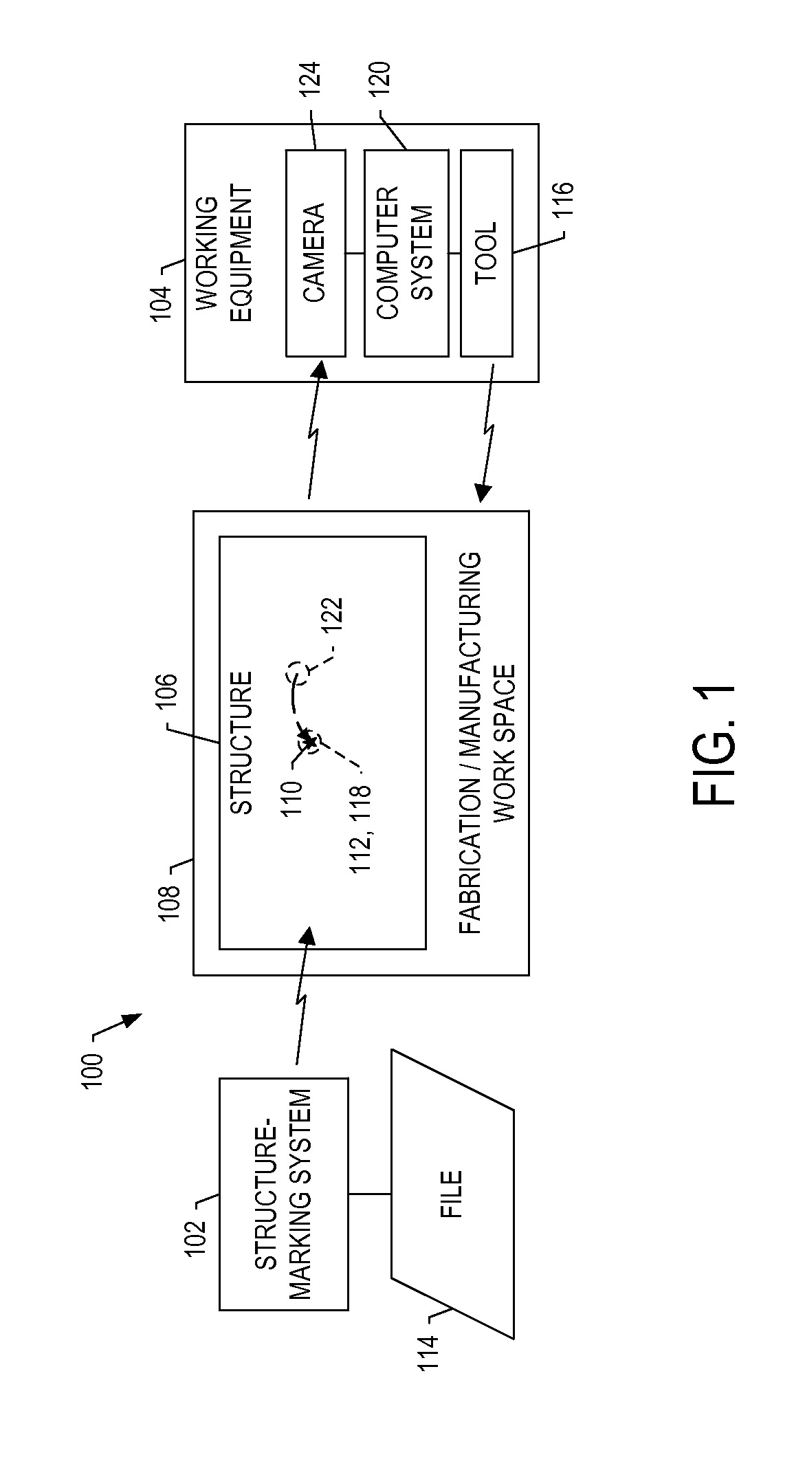
[0033]FIG. 1 illustrates a system 100 according to one example implementation of the present disclosure. As shown, the system 100 may include a structure-marking system 102 and working equipment 104 that operate on one or more structures 106 (e.g., aircraft parts) in one or more work spaces, such as a fabrication or manufacturing work space 108. In some examples, the...


PUM

PropertyMeasurementUnit
field of viewaaaaaaaaaa
focal lengthaaaaaaaaaa
transmissive optical rotary encoderaaaaaaaaaa

Abstract

Working equipment includes a tool configured to work a structure at a working location thereon, with the structure having an applied marking at a known location with a known relationship with the working location. A computer system is configured to determine placement of the structure, and accordingly position the tool into at least partial alignment with the working location, and which in at least one instance, the tool is aligned with a second, offset location. A camera is configured to capture an image of the structure and including the marking, and further including the second location with which the tool is aligned. And the computer system is configured to process the image to locate the working location, reposition the tool from the second location and into greater alignment with the located working location, and control the repositioned tool to work the structure at the located working location.

Description

TECHNOLOGICAL FIELD[0001]The present disclosure relates generally to manufacturing a product and, in particular, to manufacturing a product using markings applied thereto.BACKGROUND[0002]The accuracy with which automated manufacturing equipment is able to work parts depends largely on the quality of the location and orientation information used with the equipment. For example, with poor location and / or orientation information about a part, the most state of the art manufacturing equipment will only be able to work the part in a marginal manner. Conversely, with precise location and orientation information, a marginal piece of equipment may be able to perform well.[0003]Automated manufacturing processes requiring a moderate amount of accuracy do not call for particular part location and orientation information beyond knowing that the part has been positioned in a standard place. For these processes, the accuracy of standard part positioning allows part working with sufficient accurac...

Claims


Application Information

Patent Timeline
Patent Type & Authority Patents(United States)
IPC IPC(8): B01J19/12G01B11/14B23K26/06B23K26/082G01B11/24G06T7/00G05B19/4093G01C3/08
CPCB01J19/121B23K26/0626B23K26/082G01B11/14G01B11/24G01C3/08G05B19/40937G06T7/0004G05B2219/32025G05B2219/45134Y02P90/265B23K26/00Y02P90/02
Inventor SINGH, NAVRIT PAL
Owner THE BOEING CO
Why Eureka
Try Eureka