Carrier transportation system with brake valve device proximate to a carrier receiver

a technology of brake valve and carrier receiver, which is applied in the direction of conveyors, conveyors, transportation and packaging, etc., can solve the problems of increasing cost from both a component cost and service installation standpoint, and dissatisfaction of service providers, so as to lessen the percentage of braking distance, and reduce the overall travel time of transport carriers

Inactive Publication Date: 2008-12-04
HAMILTON AIR PRODS
View PDF22 Cites 16 Cited by
  • Summary
  • Abstract
  • Description
  • Claims
  • Application Information

AI Technical Summary

Benefits of technology

[0013]The subject matter of the present invention includes a pneumatic transportation system designed for rapid transport of the carrier through the transportation system with an increase in the percentage of non-braking and/or non-flow cushioning travel distance relative to carrier travel within the network and a corresponding lessening of the percentage of braking distance and hence a lessening in the overall transport carrier travel time in the network (e.g., a lessoning of travel time from one point (as in a teller station) to a second point (as in a customer accessible transport

Problems solved by technology

The long slow glide of the transport carrier to the customer station represents a form of delay for a customer awaiting service.
This delay creates the potential for service provider dissatisfaction, particularly customers who are waiting in a line of customers at a busy facility as in a drive-through banking facility.
Accordingly, the delay associated with

Method used


Image

  • Carrier transportation system with brake valve device proximate to a carrier receiver
  • Carrier transportation system with brake valve device proximate to a carrier receiver
  • Carrier transportation system with brake valve device proximate to a carrier receiver

Examples


Embodiment Construction

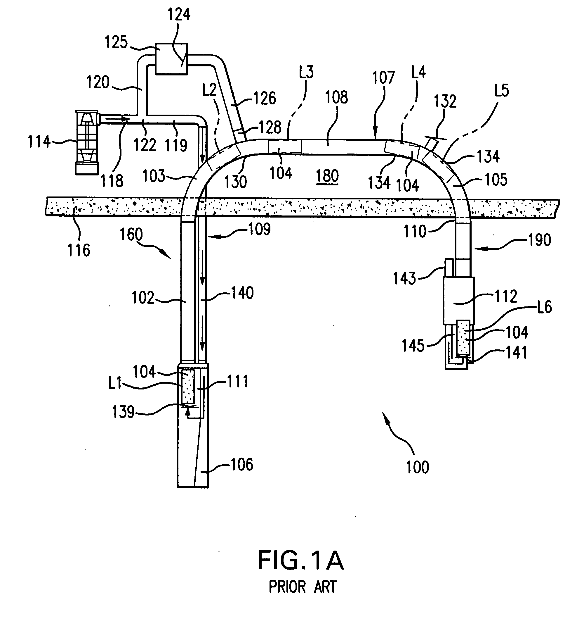
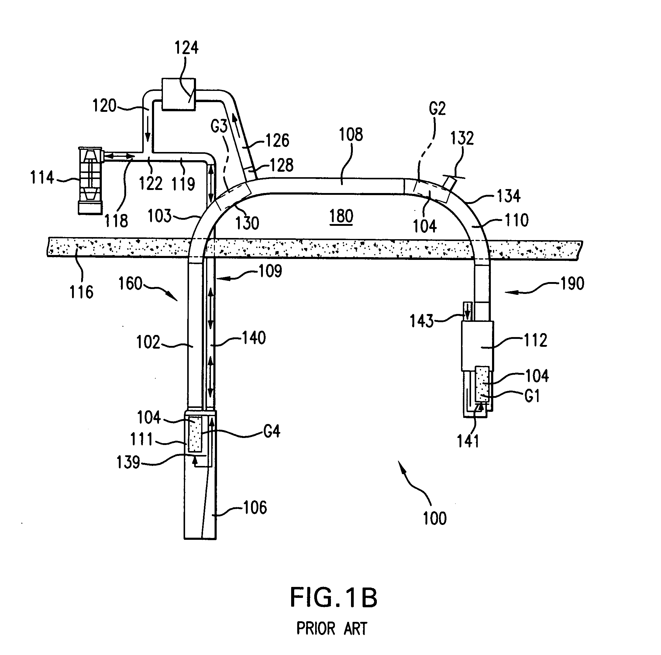
[0057]To better appreciate the advantages provided by the present invention a review is first made as to the air flow and carrier travel positioning relationship for the prior art embodiment shown in FIGS. 1A and 1B. The components featured in the bidirectional pneumatic transportation system shown in FIG. 1A are described above in the Background section. Relative to the airflow / carrier travel relationship, reference is made to Table 1 below as well as FIG. 1A which is directed at the “customer-to-teller” leg of carrier travel, while Table 2 below and FIG. 1B are directed at the “teller-to-customer” leg of travel.

[0058]Provided immediately below in Table 1 is a customer send to teller conventional system operation discussion.

TABLE 1SystemSystem operation description for a customer-to-teller transport carrier travelReferencesequence (FIG. 1A).SC1Operator (e.g., customer) presses button provided at the customer station toinitiate a customer-to-teller transport carrier mode (“CTT mode”...


PUM


Abstract

A transfer system for a carrier that features a flow supply tube in fluid communication with a flow supply generator and in fluid communication with a carrier transport tube network dimensioned for transfer reception of the carrier. The carrier transport tube network has a first carrier reception chamber provided with a first carrier stop point and a second carrier reception chamber with second carrier stop point. The flow supply tube has a single point contact with the carrier transport tube network to provide a single tube based flow connection with the carrier transport. Also, with the single point connection there can be positioned a brake valve in line with a first section of the carrier transport tube network and in line with a first section of said flow supply tube just a few feet above the stop point of one or both of the reception chambers to provide for rapid travel to the brake valve and efficient braking within just a few feet of the stop point.

Description

TECHNICAL FIELD[0001]The present application describes a carrier transportation system with an example being a bi-directional pneumatic transportation system like those used in drive-through bank teller environments or a point-to-point pneumatic transportation system as used between building floors. An embodiment of the invention features a transport carrier brake valve situated within the system close to a carrier reception chamber to provide an extended period of higher speed travel before the carrier is braked by the brake valve, and yet the carrier is sufficiently braked within that short distance to provide for a soft landing. An example is found in a brake check valve situated proximate to a banking-customer carrier reception chamber. The subject matter of the present invention also includes a brake check valve well suited for use in a pneumatic transportation system as well as a method of using that pneumatic transportation system with that brake check valve.BACKGROUND[0002]T...

Claims


Application Information

Patent Timeline
IPC IPC(8): B65G51/16
CPCB65G51/20B65G51/34
Inventor SCOTT, LOWELL
Owner HAMILTON AIR PRODS
Why Eureka
Try Eureka