Integrated double-main-cylinder line control braking system

A brake-by-wire and dual-master cylinder technology, applied in brakes, brake transmissions, transportation and packaging, etc., can solve the problems of increased brake pipeline length, slow brake pressure response, low modularization, etc., to achieve The effect of reducing the quality of the assembly, reducing the frequency of use, and reducing the working time

Active Publication Date: 2016-02-24
ZHEJIANG WANXIANG PRECISION IND +1
View PDF6 Cites 19 Cited by
  • Summary
  • Abstract
  • Description
  • Claims
  • Application Information

AI Technical Summary

Problems solved by technology

[0003] However, the existing brake-by-wire systems, such as the electronic hydraulic control system, use the electronic brake pedal, but the brake pressure is provided by the plunger pump driven by the motor, and the high-pressure accumulator is used to store the pressure, and the backup brake system More isolated solenoid valves are used, resulting in more components and higher costs for the entire system
In addition, in the existing braking system, the master cylinder and the pressure regulating unit are not integrated, the degree of modularization is not high, the length of the brake pipeline is increased, and the brake pressure response is slow

Method used


Image

  • Integrated double-main-cylinder line control braking system
  • Integrated double-main-cylinder line control braking system

Examples


Embodiment 1

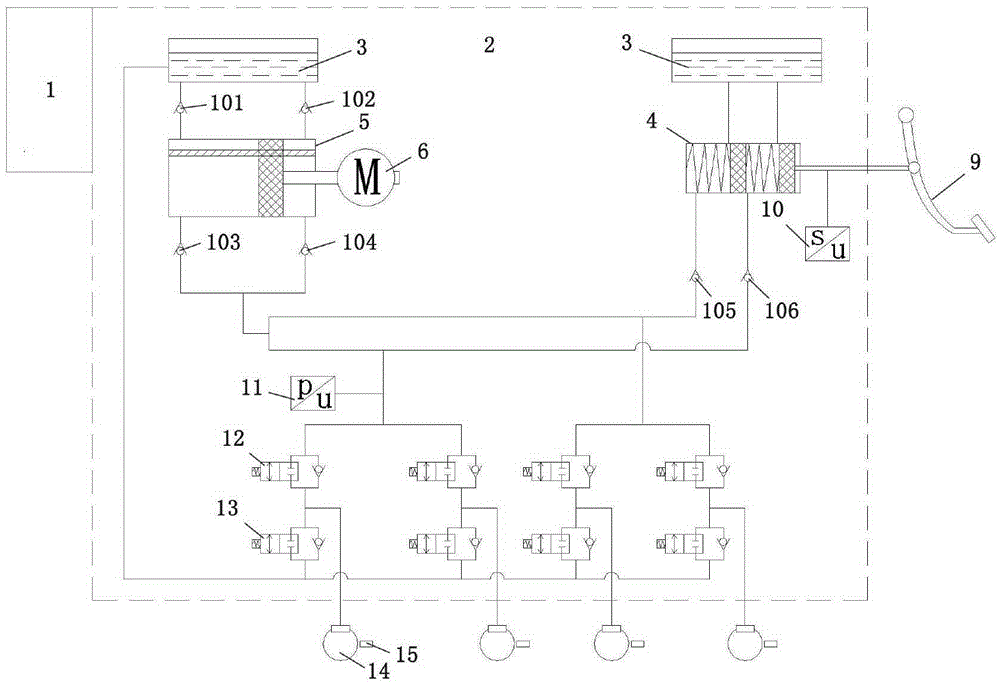
[0035] Such as figure 1 As shown, the present embodiment consists of ECU electronic control unit 1, oil pot 3, first master cylinder 4, second master cylinder 5, motor 6, electronic pedal 9, pedal displacement sensor 10, pressure sensor 11, normally open valve 12, Normally closed valve 13, wheel cylinder 14, wheel speed sensor 15, screw rod (not shown in the figure), first check valve 101, second check valve 102, third check valve 103, fourth check valve 104 , the fifth one-way valve 105, and the sixth one-way valve 106.

[0036] Wherein the oil pot 3, the first master cylinder 4, the check valve, the pressure sensor 11, the normally open valve 12, and the wheel cylinder 14 are sequentially connected to form the first brake passage, and the wheel cylinder 14 is also connected with a wheel speed sensor 15. Specifically, such as figure 1 As shown, the first master cylinder 4 is composed of a cylinder body, a piston push rod, two pistons and two return springs, and the two pist...

Embodiment 2

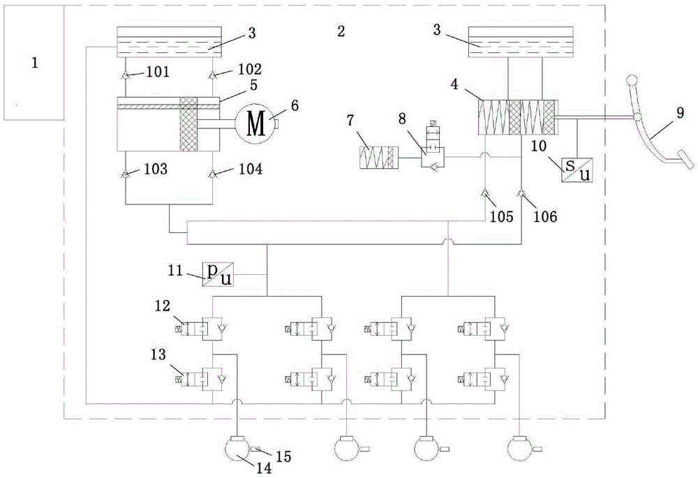
[0059] This embodiment is similar to Embodiment 1, except that this embodiment also includes a pedal feeling simulator 7 and an isolation valve 8 , and the pedal feeling simulator 7 is connected to the first master cylinder 4 through the isolation valve 8 .

[0060] In this embodiment, oil pot 3, first master cylinder 4, second master cylinder 5, motor 6, lead screw, pressure sensor 11, pedal simulator 7, one-way valve, isolation valve 8, normally open valve 12, The normally closed valves 13 are all integrated into the hydraulic adjustment unit 2 .

[0061] The specific braking process in this embodiment is as follows:

[0062] 1. Conventional braking:

[0063] When the driver depresses the electronic pedal 9, the piston push rod pushes the piston in the first master cylinder 4 to press the brake fluid into the four wheel cylinders 14 through the fifth one-way valve 105 and the sixth one-way valve 106 , the brake fluid pushes the wheel cylinder piston, and the piston pushes ...


PUM


Abstract

The invention relates to an integrated double-main-cylinder line control braking system. The system comprises an ECU electronic control unit, an electronic pedal, a pedal displacement sensor, a first braking passage, a second braking passage and a braking liquid loop. Double-main-cylinder design is adopted in the system, an assisting main cylinder, namely the second main cylinder is additionally arranged, pressure is applied through a motor and a lead screw instead of a plunger pump and an energy accumulator originally, a working cavity and a liquid supplementing cavity of the second main cylinder can be switched freely, the motor does not need to rotate forwards and reversely frequently, the service life of the motor is prolonged, and braking response time is shortened. Meanwhile, multiple braking manners can be provided through the system, especially in the micro-braking process, the assisting main cylinder does not work, a conventional main cylinder applies pressure, the working time of the motor is shortened, and the service life of the motor is prolonged.

Description

technical field [0001] The invention relates to the field of vehicle brake systems, in particular to an integrated double master cylinder wire brake system. Background technique [0002] The car braking system is closely related to the safety of the car. The traditional braking system requires the driver to apply the braking force, which is amplified by the vacuum booster to achieve vehicle braking. Compared with vacuum boosting, the boosting power of the electric power boosting braking system is controllable. When braking energy recovery is required, the boosting motor can be controlled to achieve less or no boosting as needed to reduce the pressure output of the master cylinder. The control-by-wire system cancels the mechanical connection of the traditional braking system, and has the characteristics of simpler structure, more flexible control, shorter response time, better braking performance, and simple maintenance. [0003] However, the existing brake-by-wire systems, ...

Claims


Application Information

Patent Timeline
Patent Type & Authority Applications(China)
IPC IPC(8): B60T13/12B60T13/74
CPCB60T13/12B60T13/745
Inventor 潘劲吴文浩刘伟吴志强
Owner ZHEJIANG WANXIANG PRECISION IND
Why Eureka
Try Eureka