Device capable of adjusting vertical loads of four wheels of automobile

A vertical load and adjustable technology, applied in the direction of the body, vehicle parts, streamlined body, etc., can solve problems such as slippage, large vehicle roll, and vertical load that cannot be controlled independently, so as to suppress the body roll and increase the cornering speed , Improve the effect of handling stability

Pending Publication Date: 2018-03-06
FUZHOU UNIV
View PDF9 Cites 19 Cited by
  • Summary
  • Abstract
  • Description
  • Claims
  • Application Information

AI Technical Summary

Problems solved by technology

However, this kind of front fender or rear wing adopts one integral fender, which can only control the two wheels of the front axle or the two wheels of the rear axle at the same time, and cannot control the vertical load of each wheel independently, which has certain limitations.
[0003] In addition, when the car is cornering at high speed, due to the effect of centrifugal force, the vertical load of the wheel on the inside of the curve decreases, while the vertical load of the wheel on the outside of the curve increases, and the car is prone to large roll, extreme Situations that result in slipping beyond the adhesion limit of the wheel on the outside of the curve
However, this cannot be mitigated by the fact that the downforce on the left and right sides of the car is the same from the front fender or the rear wing

Method used


Image

  • Device capable of adjusting vertical loads of four wheels of automobile
  • Device capable of adjusting vertical loads of four wheels of automobile
  • Device capable of adjusting vertical loads of four wheels of automobile

Examples


Embodiment Construction

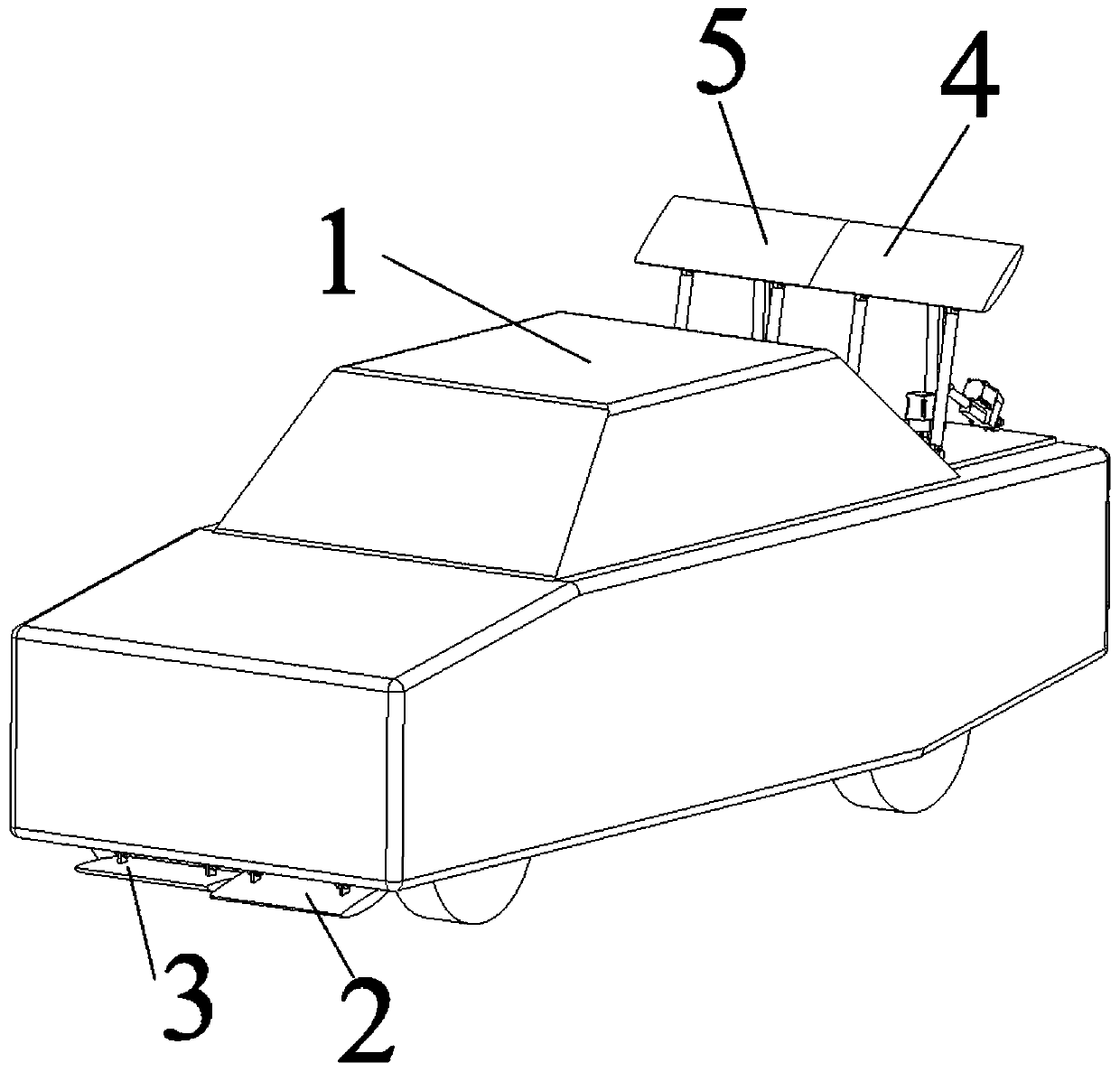
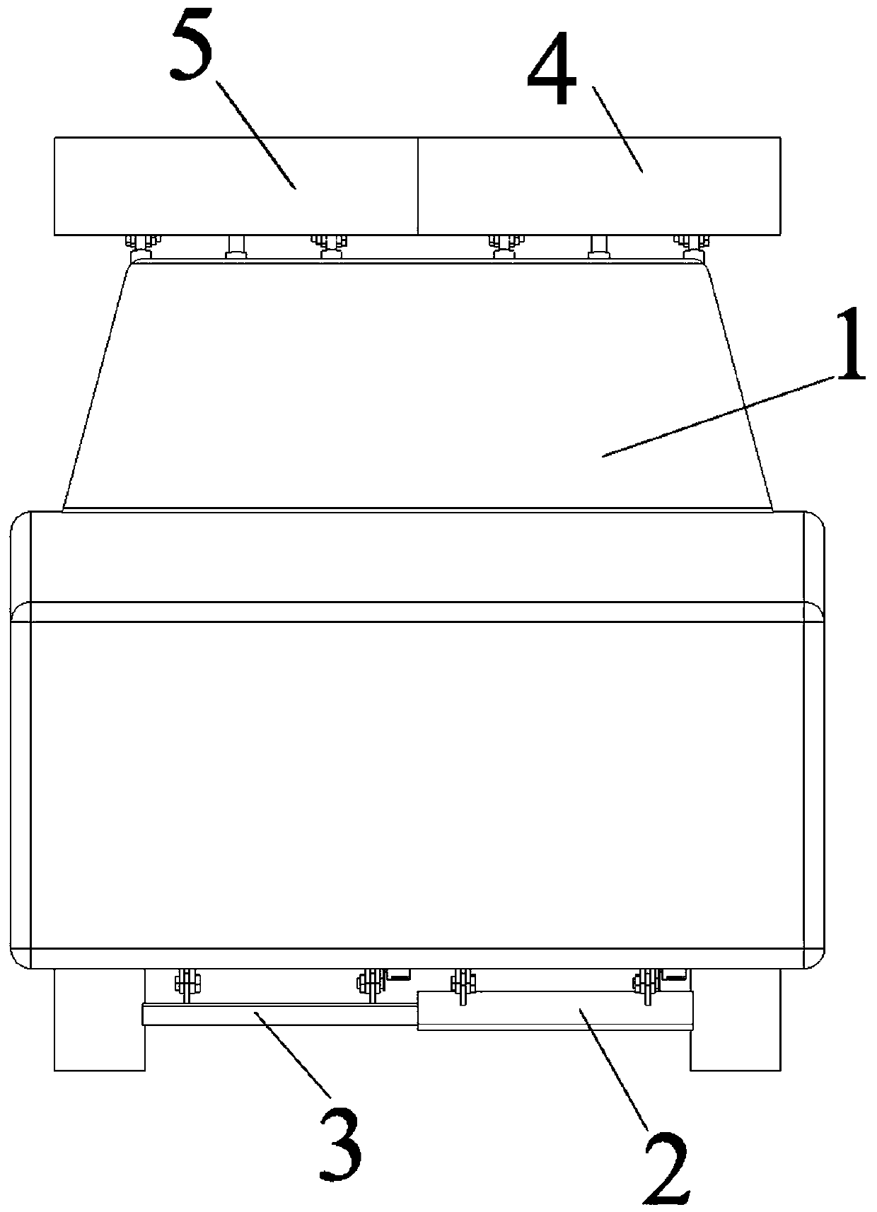
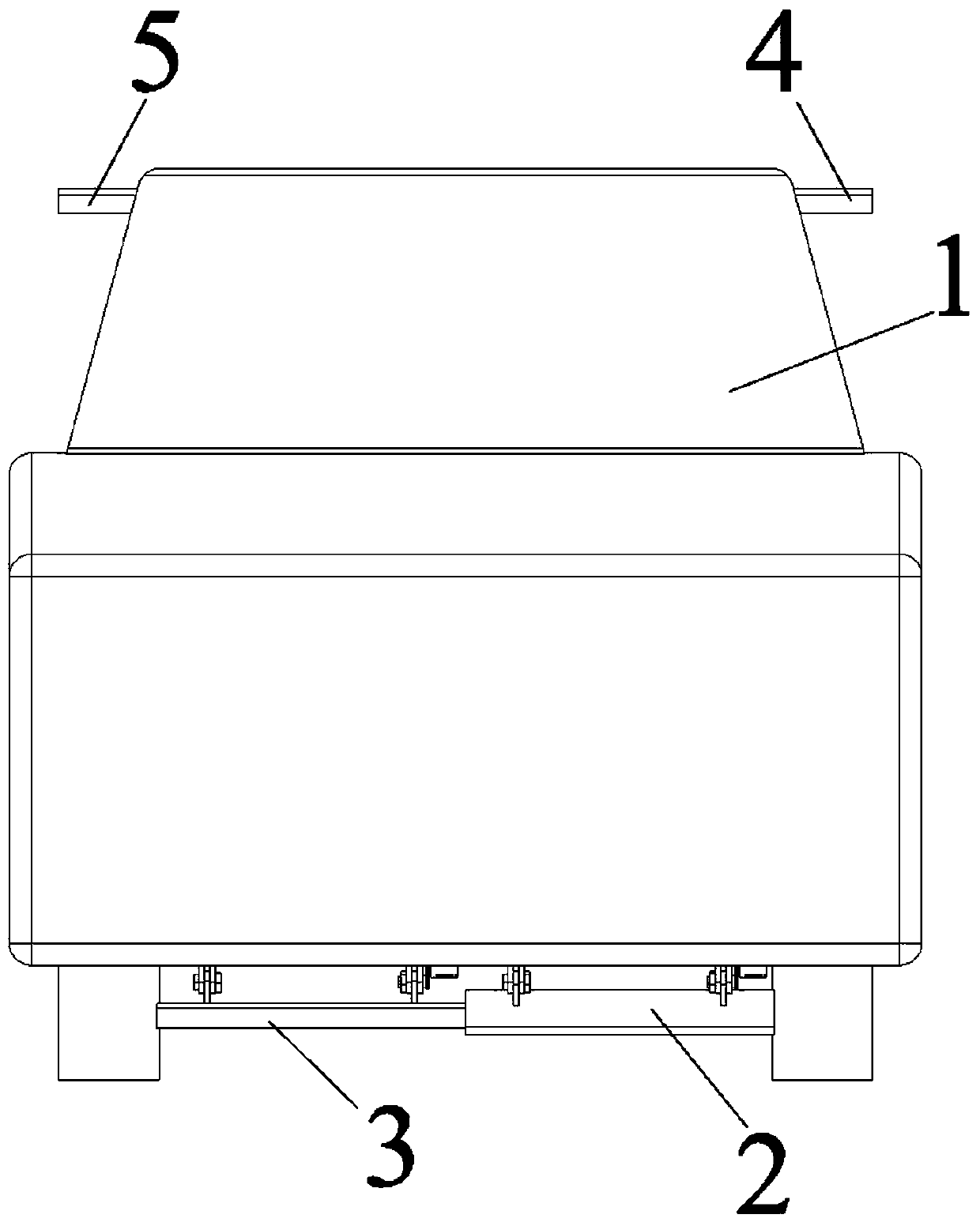
[0033] Such as Figure 1-8Shown, a kind of adjustable automobile four-wheel vertical load device, described device comprises front left wing plate 2, front right wing plate 3, rear left wing plate 4, rear right wing plate 5, wing plate attitude adjustment mechanism and vehicle-mounted ECU; The left wing and the front right wing are located at the front of the vehicle body 1 and in front of the front wheels at the lower end of the chassis. The front left wing and the front right wing are respectively adjacent to the left front wheel and the right front wheel; on the left and right sides of the rear of the vehicle body; the wing plate attitude adjustment mechanism is connected with the front left wing plate and the front right wing plate to adjust the angle of attack; the vehicle-mounted ECU is connected with the wing plate attitude adjustment mechanism; the wing plate attitude adjustment mechanism is connected with the rear wing plate The left wing plate and the rear right wing...


PUM


Abstract

The invention provides a device capable of adjusting vertical loads of four wheels of an automobile. The device comprises a front left wing plate, a front right wing plate, a rear left wing plate, a rear right wing plate, a wing plate posture adjusting mechanism and an automobile-mounted ECU. The front left wing plate and the front right wing plate are arranged on the front portion of an automobile body and located in front of front wheels on the lower end face of a chassis, the front left wing plate is adjacent to the left front wheel, and the front right wing plate is adjacent to the right front wheel. The rear left wing plate and the rear right wing plate are arranged on the left side and the right side of the rear portion of the automobile body. The wing plate posture adjusting mechanism is connected with the front left wing plate and the front right wing plate so as to adjust the attack angles of the front left wing plate and the front right wing plate. The automobile-mounted ECUis connected with the wing plate posture adjusting mechanism. The wing plate posture adjusting mechanism is connected with the rear left wing plate and the rear right wing plate so as to adjust the attack angles and the position height of the rear left wing plate and the rear right wing plate. When the automobile travels, the front left wing plate, the front right wing plate, the rear left wing plate and the rear right wing plate convert airflow force born by the wing plates into pressure and / or resistance applied to the automobile body; and aerodynamic force can be used for applying pressureor resistance to the automobile in the automobile traveling process so as to enhance the controllability of the automobile.

Description

technical field [0001] The invention relates to the technical field of automobiles, in particular to an adjustable four-wheel vertical load device for automobiles. Background technique [0002] When the car is running, due to the shape and structure characteristics of the car itself, an upward lift will be generated, resulting in a decrease in the vertical load on the four wheels, thereby affecting the handling stability. According to F x =μF Z (F x : longitudinal driving force; μ: road surface adhesion coefficient; F Z : single tire vertical load), when the road surface adhesion coefficient μ is constant, the single tire vertical load F Z When changing, the longitudinal driving force F x change. When the longitudinal driving force F x When it gets smaller, it affects the driving force of the car. According to F y =αC r (F y : Lateral force; α: Slip angle; C r : cornering stiffness), and the cornering stiffness increases as the vertical load increases, and vice v...

Claims


Application Information

Patent Timeline
Patent Type & Authority Applications(China)
IPC IPC(8): B62D35/00B60T1/16
CPCB62D35/005B62D35/007B60T1/16
Inventor 吴乙万陈正强杨康彭富豪
Owner FUZHOU UNIV
Why Eureka
Try Eureka