MRI compatible robot with calibration phantom and phantom

a robot and calibration technology, applied in the field of medical robots, can solve the problems of not providing a solution for each of the robots, and each has some significant limitations

Active Publication Date: 2009-12-31
CHINA SUPERROBOTICS LTD +1
View PDF24 Cites 13 Cited by
  • Summary
  • Abstract
  • Description
  • Claims
  • Application Information

AI Technical Summary

Problems solved by technology

Some medical robots have been developed however each has some significant limitations.
None of these robots provides a solution using ultrasonic motors that are positionable inside the bore near the isocentre of the MRI.

Method used


Image

  • MRI compatible robot with calibration phantom and phantom
  • MRI compatible robot with calibration phantom and phantom
  • MRI compatible robot with calibration phantom and phantom

Examples


Embodiment Construction

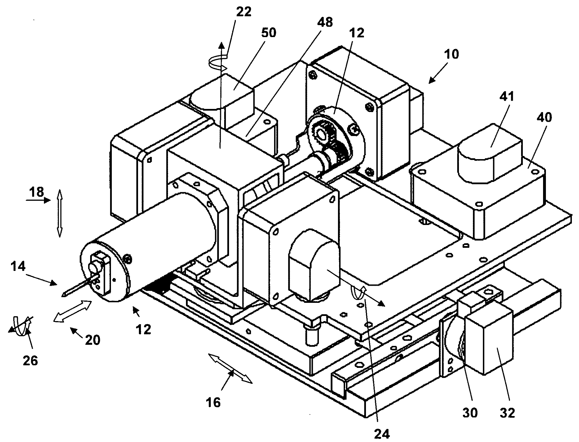
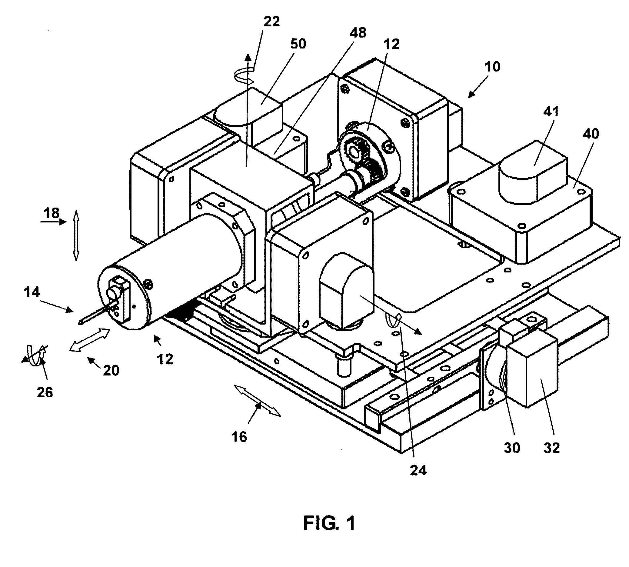
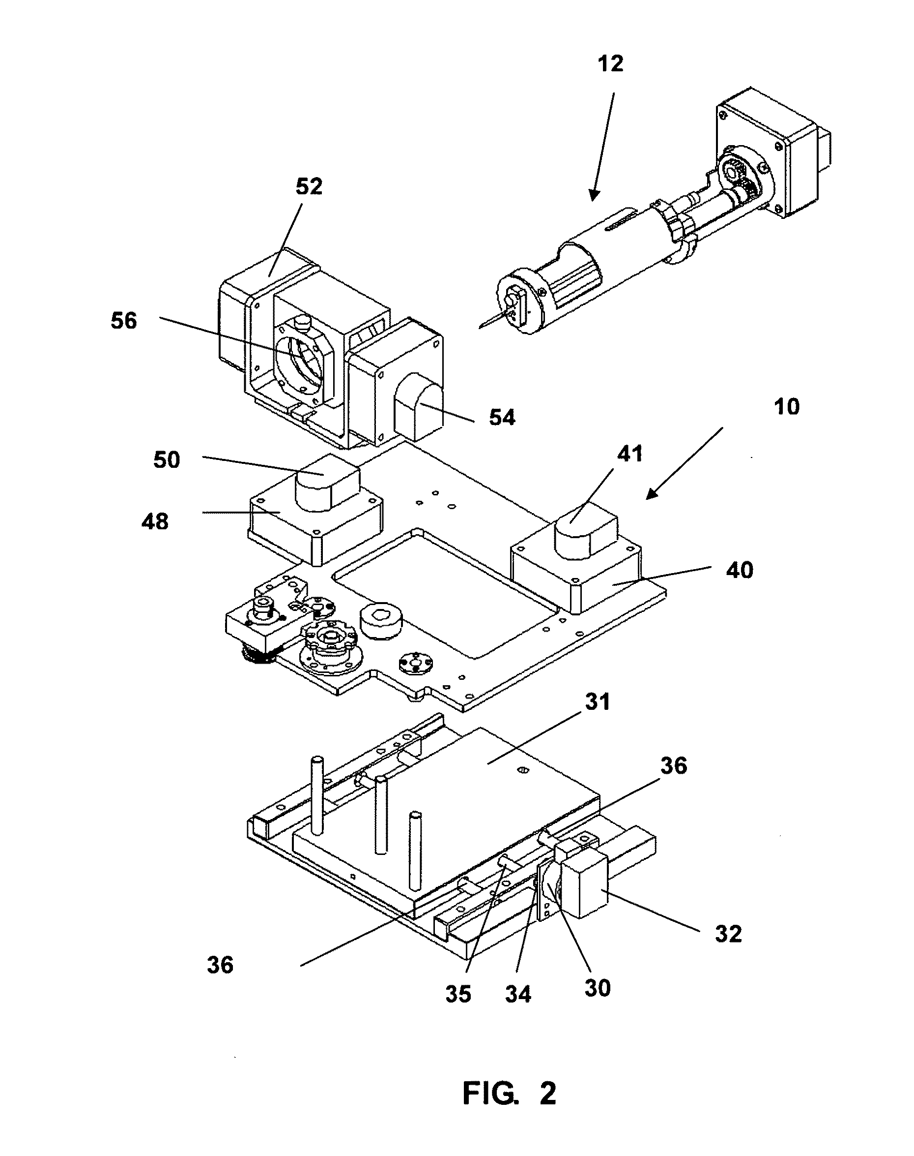
[0062]The present invention relates to performing medical procedures remotely using a robot under the guidance of magnetic resonance imaging (MRI). One function of the robot is to deliver one or more medical device to a location within the body as selected based on magnetic resonance (MR) images of the body. The MR images are also used to monitor the intervention and the therapy provided in real-time. The robotic device is MRI compatible whilst inside the MRI scanner.

[0063]In one application, the robotic device is used for tissue ablation. In this application, the objective is to destroy a particular region of tissue that may contain a certain size and type of cancerous tumor through either heating or cooling. In the present context, the robot will deliver a heating or cooling device to the MRI-specified location. Heating or cooling will then destroy the tissue in the targeted region. In this application, the temperature change in tissue is monitored as the heating / cooling is being ...


PUM


Abstract

A medical robot for use inside an MRI includes a horizontal motion assembly, a vertical motion assembly and a controller. The horizontal motion assembly and the vertical assembly each includes a motion joint, an ultrasonic motor operably connected to the motion joint and an encoder operably connected to the ultrasonic motor. The motor and encoder are positioned proximate to the joint of the respective horizontal motion assembly and vertical motion assembly. Each motor has a cross section positioned in one of the axial and sagittal plane of the MRI. A medical instrument assembly is operably connectable to one of the moving joint of the vertical motion assembly. The controller is operably connected to the horizontal motion joint and the vertical motion joint and it is adapted to be powered off when the magnetic resonance imager is being used to collect images.

Description

CROSS REFERENCE TO RELATED PATENT APPLICATION[0001]This patent application relates to U.S. Provisional Patent Application Ser. No. 61 / 129,319 filed on Jun. 18, 2008 entitled MEDICAL ROBOT FOR USE IN A MRI which is incorporated herein by reference in its entirety.FIELD OF THE INVENTION[0002]This invention relates to medical robots and in particular medical robots for use in a magnetic resonance imaging device.BACKGROUND OF THE INVENTION[0003]Medical resonance imaging (MRI) devices are well known medical tools and are used extensively for diagnostic purposes. More recently it has become evident that it would be advantageous to provide a device that could be used within a close-bore MRI to perform surgery by remote control. Some medical robots have been developed however each has some significant limitations. Specifically there have been suggested some medical robots that use motors that are positioned 1 to 2 meters from the isocentre of the MRI (in fact outside the bore) and are actua...

Claims


Application Information

Patent Timeline
Patent Type & Authority Applications(United States)
IPC IPC(8): A61B5/055A61B19/00
CPCA61B19/2203A61B2017/00084A61B2017/00725A61B2018/2261G01R33/58A61B2019/2223A61B2019/507A61B2019/5236A61B2019/2211A61B2034/301A61B34/30A61B34/37A61B2034/107A61B2090/374A61B90/00A61B90/39A61B5/055A61B17/34A61B18/20B25J13/06A61B2017/3409
Inventor GOLDENBERG, ANDREW A.YANG, YIMA, LIANGTRACHENBERG, JOHNKUCHARCZYK, WALTERHAIDER, MASOOMSUSSMAN, MARSHALL STEPHENLINDNER, URIWEERSINK, ROBERT ANTHONIE
Owner CHINA SUPERROBOTICS LTD
Why Eureka
Try Eureka