Flat compass for marking large arcsand circles

Inactive Publication Date: 2010-01-07
CONTRERAS AMAURY D
View PDF21 Cites 19 Cited by
  • Summary
  • Abstract
  • Description
  • Claims
  • Application Information

AI Technical Summary

Benefits of technology

[0013]It is an object of the flat compass to provide a compass for marking an arc where the radius of the arc is nearly infinite. Rulers are used in lengths of 12 inches or less to eight feet or more. These rule

Problems solved by technology

These marking tools are crude and the accuracy of the mark can change as the string wraps around the anchor (nail) and the angle of the pencil changes as the user marks the arc.
Two major problems exist with this type of marking system.
The first problem is that the angle of the pencil or scribe can change since it is not supported in a flat parallel orientation with the surface being marked and the second problem is that the size of the arc is limited by the length of the ruler or stick.
While th

Method used


Image

  • Flat compass for marking large arcsand circles
  • Flat compass for marking large arcsand circles
  • Flat compass for marking large arcsand circles

Examples


first embodiment

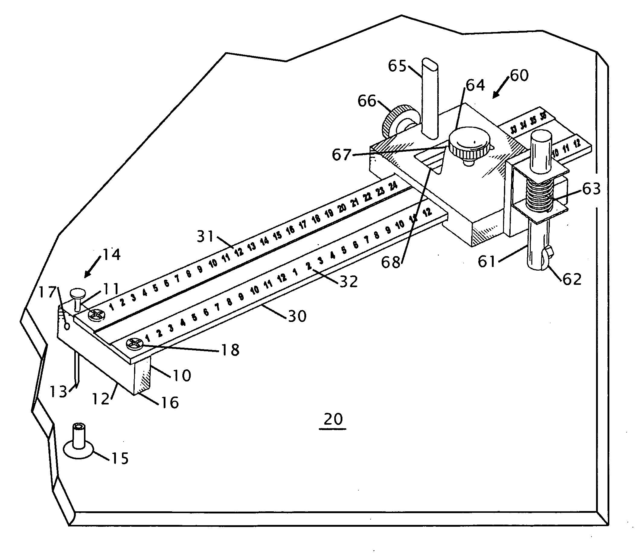
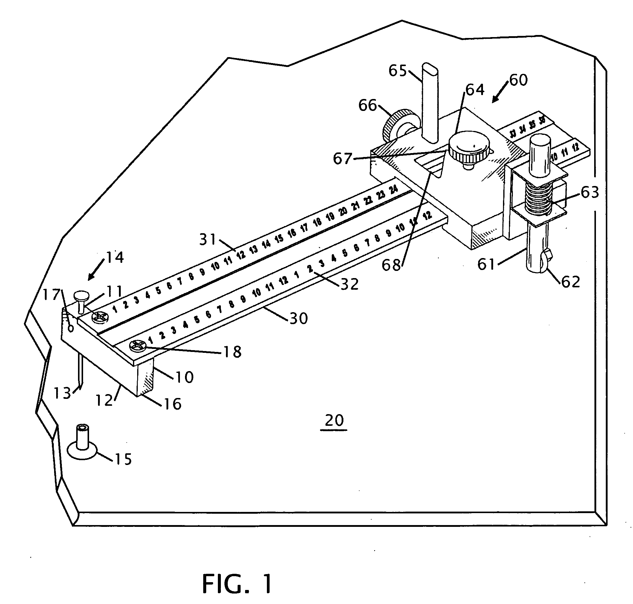
[0025]FIG. 1 shows an isometric view of the flat compass. The flat compass has an anchor 10 having an elongated shank 11 in combination with an enlarged flanged base 12 having a means for the function of limiting how far the shank is set into an essentially flat surface 20. The elongated shank 11 further has a tapered tip 13. The elongated shank 11 is from a nail 14. The shank 11 is limited to extend between 0.01 and 1.00 inches into the essentially flat surface 20 while this length of extension is broad it allows the elongated shank to extend into a variety of surfaces. In one contemplated embodiment a suction cup 15 can be placed onto the end of the elongated shank 13 for securing the flat compass for marking glass or other material where the elongated shank may not penetrate or is penetration is undesirable. Retaining screws 18 hold the anchor components onto a beam 30.

[0026]At an engagement length of 2 inches the elongated shank can penetrate and is rigidly secured into a semi s...

second embodiment

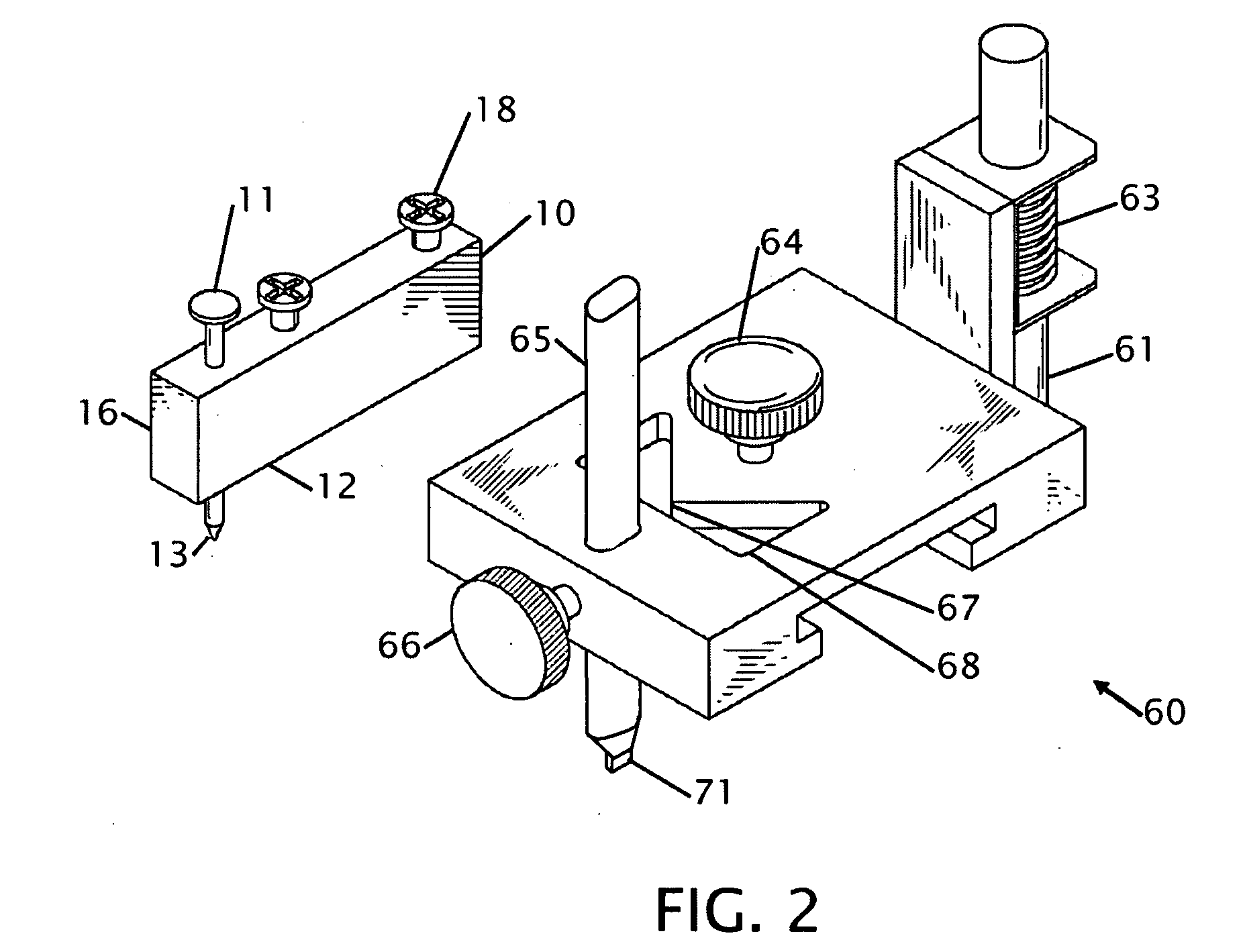
[0031]FIG. 2 shows an isometric view of the same embodiment from FIG. 1 without the beam and FIG. 3 shows an isometric view of the flat compass without the beam. These figures show the opening in the side of the head 60 where the beam would slide through to locate the head 60 on the beam (not shown). The anchor 10 is shown with the two retaining screws 18 that secure the beam onto the anchor 10. The top of the elongated shank 10 and the tapered tip of the elongated shank 11 or nail (14) is visible extending through the anchor 10. The tip 13 exists in a linear relationship with the marking tip 71 of the marking means 65. The anchor 10 has an enlarged flange base 12 made from a block of material 16. While the anchor is shown as a rectangular block of material other shapes are contemplated that will perform equivalently. In FIG. 2 the vertical shank 61 extends from a separate block of material whereas in FIG. 3 the vertical shank 61 extends through the head block. The bottom of the sha...


PUM


Abstract

An improvement in a compass that marks large radius arcs is disclosed. The compass is for marking on flat surfaces like the ground and walls where higher degree of accuracy for the radius or circle is desired. More particularly, the present flat compass allows a person to create a virtually unlimited radius arc using a center point and a rigid arm with a marking tip. The flat compass uses a rigid flat ruler with an embeddable anchor, such as a nail, on one end and a marking tip on the other that keeps the rigid arm essentially parallel with the marking surface as the surface is being marked. The marking tip is movable along the length of the rigid flat ruler. Multiple rulers can be connected to increase the size of the arc that will be drawn.

Description

[0001]This application claims the benefit of Design Patent Application 29 / 288,247 filed Jun. 6, 2007, now D572,611 issued Jul. 8, 2008, and Design Patent Application 29 / 307,106 filed Apr. 1, 2008 the entire contents of which is hereby expressly incorporated by reference herein.STATEMENT REGARDING FEDERALLY SPONSERED RESEARCH OR DEVELOPMENT[0002]Not ApplicableTHE NAMES OF THE PARTIES TO A JOINT RESEARCH AGREEMENT[0003]Not ApplicableINCORPORATION-BY-REFERENCE OF MATERIAL SUBMITTED ON A COMPACT DISC[0004]Not ApplicableDESCRIPTION[0005]1. Field of the Invention[0006]This invention relates to improvements in a flat compass for drawing large arcs and circles. More particularly, the present flat compass allows a person to create a virtually unlimited radius arc using a center point and a rigid arm with a marking tip. This is ideal for use in construction industry where precision of a pencil at the end of a string provides limited accuracy.[0007]2. Background of the Invention[0008]Most arc ...

Claims


Application Information

Patent Timeline
IPC IPC(8): B43L9/04
CPCB43L9/007B43L9/245B43L9/24B43L9/04
Inventor CONTRERAS, AMAURY D.
Owner CONTRERAS AMAURY D
Why Eureka
Try Eureka