Supercharge Your Innovation With Domain-Expert AI Agents!

Anti-Rotation Feature for an Engine Tappet

a technology of anti-rotation and engine tappet, which is applied in the direction of valve arrangement, fuel injection apparatus, charge feed system, etc., can solve the problems that it has not been proved economical to provide a non-rotation flat in the engine bore, and achieve the effect of improving wear resistan

Inactive Publication Date: 2010-01-07
DELPHI TECH INC
View PDF4 Cites 7 Cited by
  • Summary
  • Abstract
  • Description
  • Claims
  • Application Information

AI Technical Summary

Benefits of technology

[0008]Briefly described, a hardened anti-rotation feature in accordance with the present invention comprises a first portion for extending outwards from the surface of a tappet and a second or pin portion for extending into a mounting hole in the tappet. Unlike somewhat similar prior art anti-rotation features, however, the first portion of the present improved feature extends longitudinally to either or both sides of the mounting hole such that when the feature and tappet are installed in an engine bore, the entire feature is prevented from rotation within the hole. Thus, the second portion extending orthogonally from the first portion into the mounting hole need not be particularly close-fitting to the hole. In a presently preferred embodiment, the first portion is substantially semi-cylindrical, having a convex cylindrical outer surface for fitting the walls of a semi-cylindrical channel in the engine bore and a concave cylindrical inner surface for fitting the outer wall of the tappet. The pin portion is preferably cylindrical for ease of fabrication of both the pin portion and the tappet hole. Obviously, other cross-sectional shapes, such as rectangular, oval, and the like as may be desired for any particular application are fully comprehended by the present invention. The anti-rotation feature may further be hardened for improved wear resistance.

Problems solved by technology

Because a cylindrical engine bore is the simplest and least expensive shape for receiving a tappet, it has not proved economical to provide a non-rotation flat in an engine bore for mating with a non-rotation flat on a tappet.
Because the tolerances between the two hardened parts is too tight for the parts to be machined to size cost-effectively, in practice suitable matching of pin to hole is achieved by the laborious process of sorting through the manufactured tolerances of tappet holes and pin diameters.

Method used


Image

  • Anti-Rotation Feature for an Engine Tappet
  • Anti-Rotation Feature for an Engine Tappet
  • Anti-Rotation Feature for an Engine Tappet

Examples


Embodiment Construction

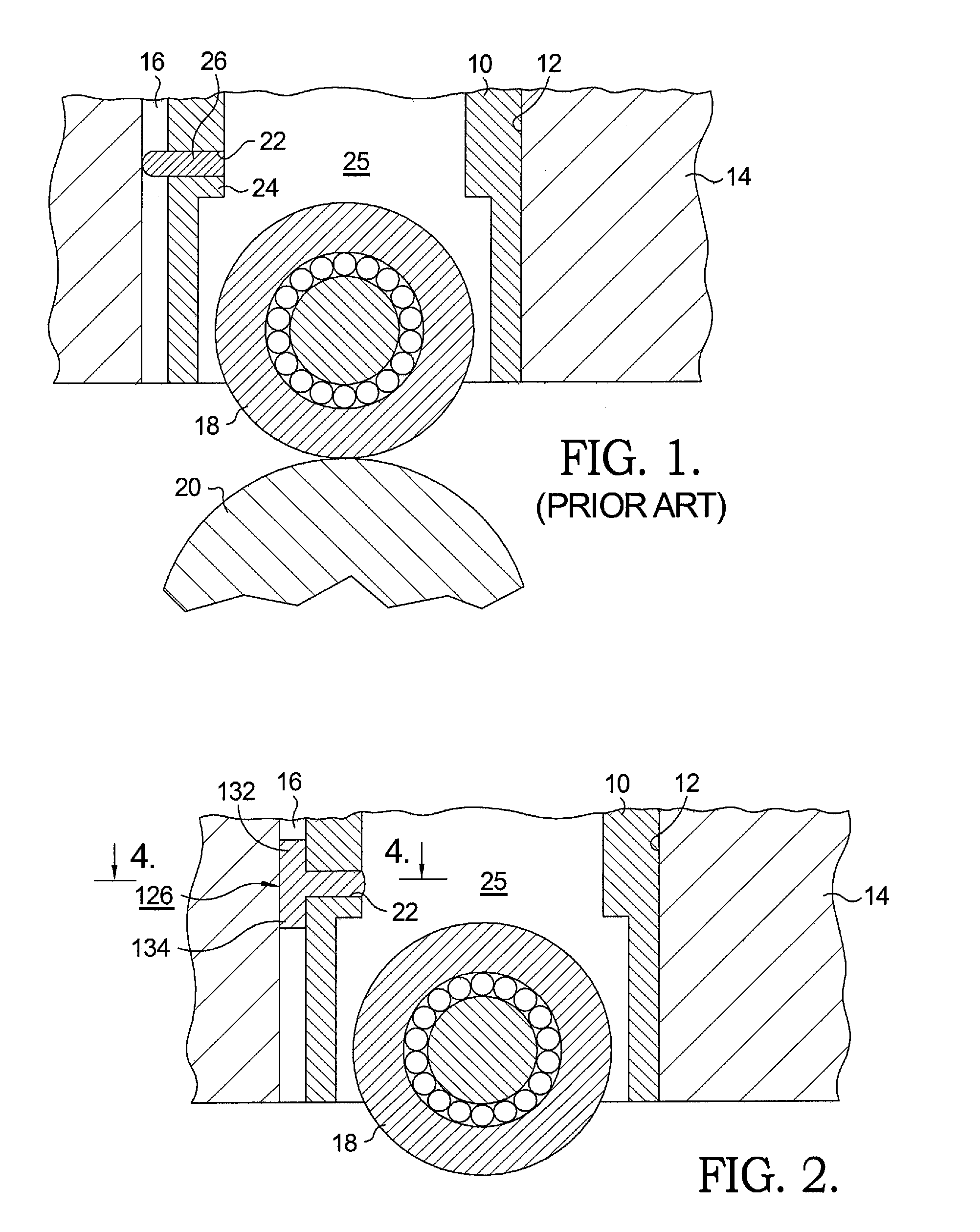
[0015]Referring to FIG. 1, a tappet 10 is slidably disposed in a bore 12 in an engine 14. Longitudinally adjacent and parallel to bore 12 is an anti-rotation channel 16 opening into bore 12. Tappet 10 is provided with a roller 18 for riding on the surface of a camshaft lobe 20 and a transverse hole 22 extending through wall 24 into a chamber 25. In accordance with the prior art, a close-fitting hardened pin 26 is press-fit into hole 22 and extends into channel 16 to prevent rotation of tappet 10 within bore 12, thus maintaining alignment of roller 18 on cam lobe 20.

[0016]The problems inherent in this prior art arrangement, which are eliminated by the present invention, are discussed above.

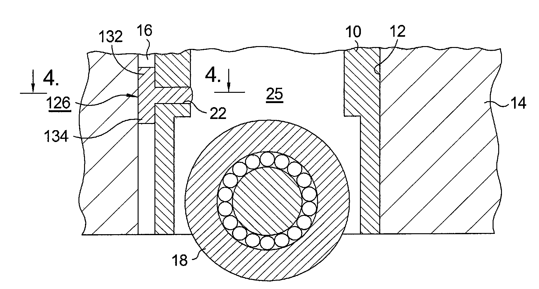
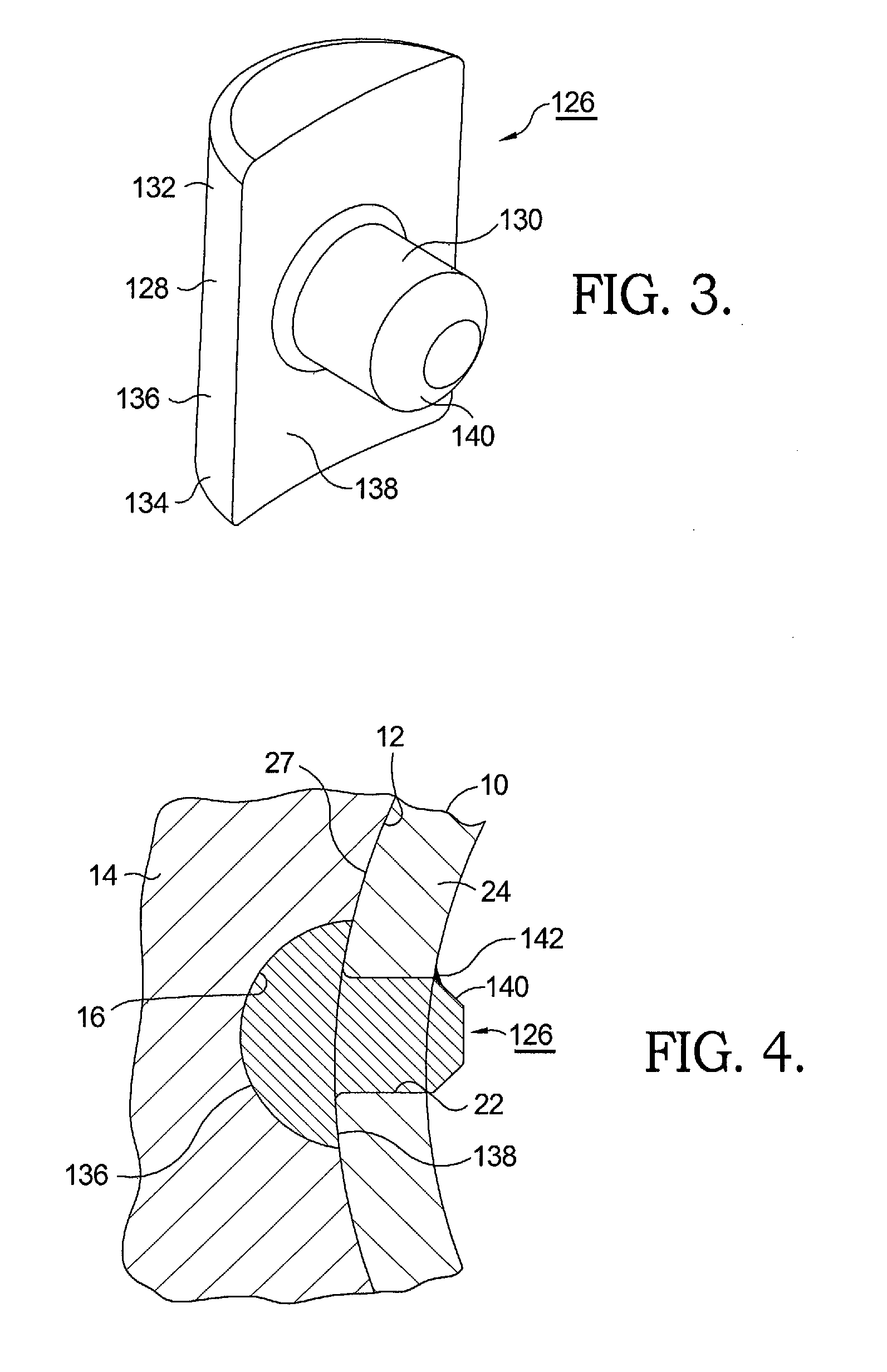
[0017]Referring now to FIGS. 2 through 4, an anti-rotation feature 126 in accordance with the present invention replaces prior art pin 26. Feature 126 comprises a first portion 128 for extending outwards from the surface of a tappet into channel 16, which in the presently-preferred example is cylin...


PUM


Abstract

An alignment feature for preventing in-bore rotation of an engine tappet. A first portion extends outwards from a tappet and a second portion extends into a hole in the tappet. The first portion extends longitudinally past the mounting hole such that when the feature and tappet are installed in an engine bore, the entire feature is prevented from rotation within the hole. The second portion extending orthogonally from the first portion into the mounting hole need not be close-fitting to the hole. The first portion may be substantially semi-cylindrical, having a convex cylindrical outer surface for fitting the walls of a semi-cylindrical channel in the engine bore and a concave cylindrical inner surface for fitting the outer wall of the tappet. The pin portion is preferably cylindrical. Other pin shapes are possible. The alignment feature may or may not be hardened.

Description

RELATIONSHIP TO OTHER APPLICATIONS AND PATENTS[0001]This application claims the benefit of U.S. Provisional Patent Application Ser. No. 61 / 134,133, filed Jul. 7, 2008, which is hereby incorporated by reference in its entirety.TECHNICAL FIELD[0002]The present invention relates to tappets that are reciprocally slidable in bores in internal combustion engines; more particularly, to such tappets that must maintain rotational orientation in such bores during reciprocation; and most particularly, to a simple and inexpensive anti-rotation feature for attachment to a tappet during manufacture of an engine.BACKGROUND OF THE INVENTION[0003]Tappets are well known in the engine arts for converting rotary motion of camshaft lobes into reciprocating linear motion that is useful in driving engine combustion valves or other engine devices, for example, fuel pumps for supplying high pressure fuel rails. As used herein, the generic term “tappet” should be taken to mean any such cam-actuated linear-ac...

Claims


Application Information

Patent Timeline
IPC IPC(8): F01L1/14
CPCF01L1/14F01L2107/00F01L2105/00F02M2200/8015F01L2307/00F01L2305/00
Inventor KUNZ, TIMOTHY W.BAUMAN, WILLIAM D.DRAEGER, DAVIDSKILLING, MICHAEL J.
Owner DELPHI TECH INC
Features
  • R&D
  • Intellectual Property
  • Life Sciences
  • Materials
  • Tech Scout
  • Unparalleled Data Quality
  • Higher Quality Content
  • 60% Fewer Hallucinations
Learn More