Car battery array having a plurality of connected batteries

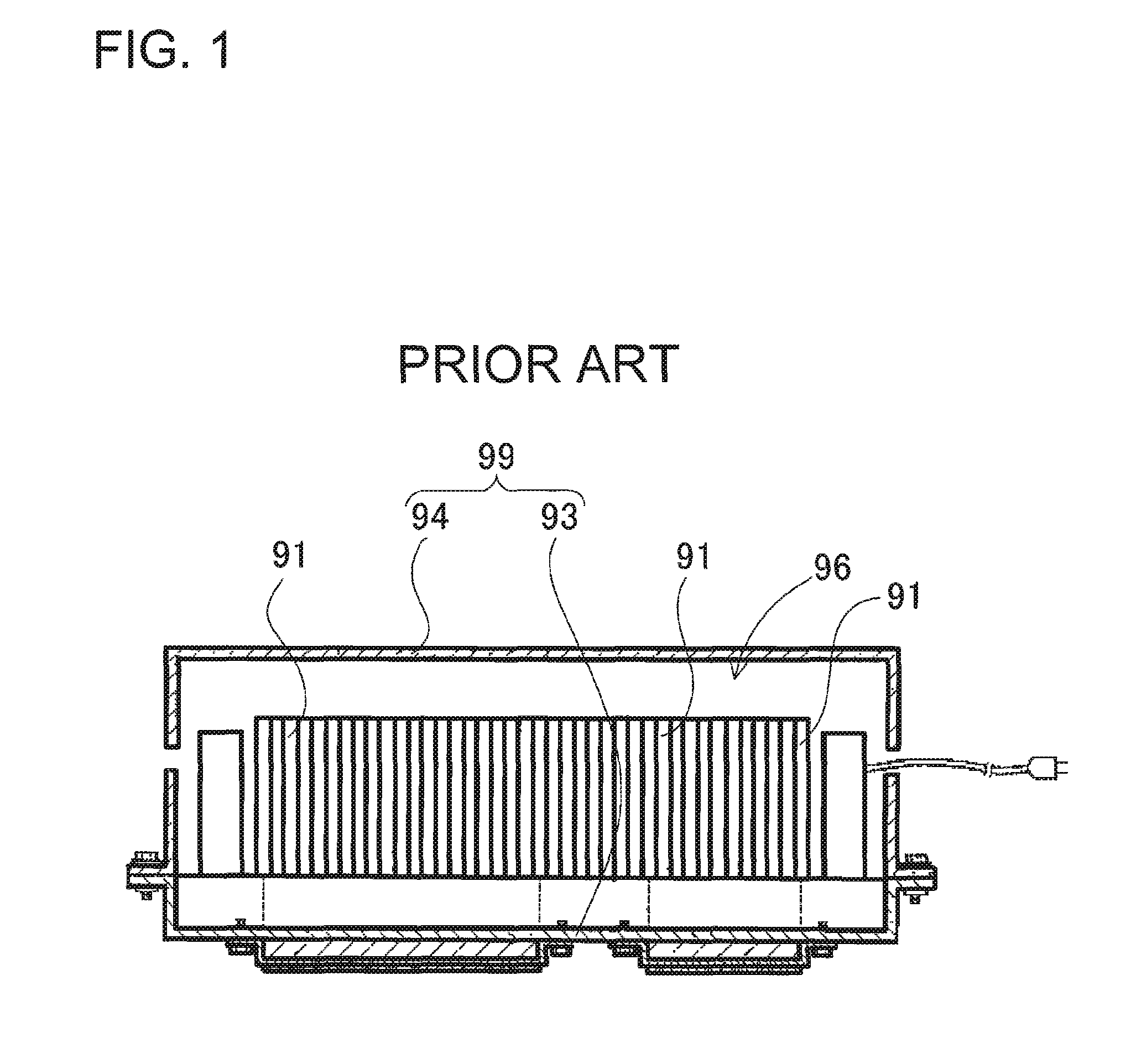
a technology of connected batteries and car batteries, applied in the direction of current conducting connections, cell components, propulsion by batteries/cells, etc., can solve the problems of large overall weight and extremely heavy external cases, and achieve the effect of light weight and strong construction

Active Publication Date: 2010-01-07
SANYO ELECTRIC CO LTD
View PDF22 Cites 88 Cited by
  • Summary
  • Abstract
  • Description
  • Claims
  • Application Information

AI Technical Summary

Benefits of technology

[0007]The car battery array of the present invention is provided with the following structure to achieve the object described above. The car battery array is provided with battery blocks 2, 32 having a plurality of connected batteries 1; a first load-bearing plate 3, 33 on which battery blocks 2, 32 are mounted; a second load-bearing plate 4, 34 that attaches to both sides of the first load-bearing plate 3, 33 and covers the upper surfaces of the battery blocks 2, 32; and a reinforcing rod 5, 35 disposed between, and connected to the second load-bearing plate 4, 34 and the battery blocks 2, 32 to join the second load-bearing plate 2, 32 to the battery blocks 2, 32. The battery array has both sides of the first load-bearing plate 3, 33 and the second load-bearing plate 4, 34 connected together, a battery compartment 6, 36 is established inside the load-bearing plates, and battery blocks 2, 32 are disposed in that battery compartment 6, 36. Battery blocks 2, 32 disposed in the battery compartment 6, 36 are mounted on the first load-bearing plate 3, 33 and are joined to the second load-bearing plate 4,

Problems solved by technology

This type of battery array is provided with many high capacity battery cells resulting in a

Method used


Image

  • Car battery array having a plurality of connected batteries
  • Car battery array having a plurality of connected batteries
  • Car battery array having a plurality of connected batteries

Examples


first embodiment

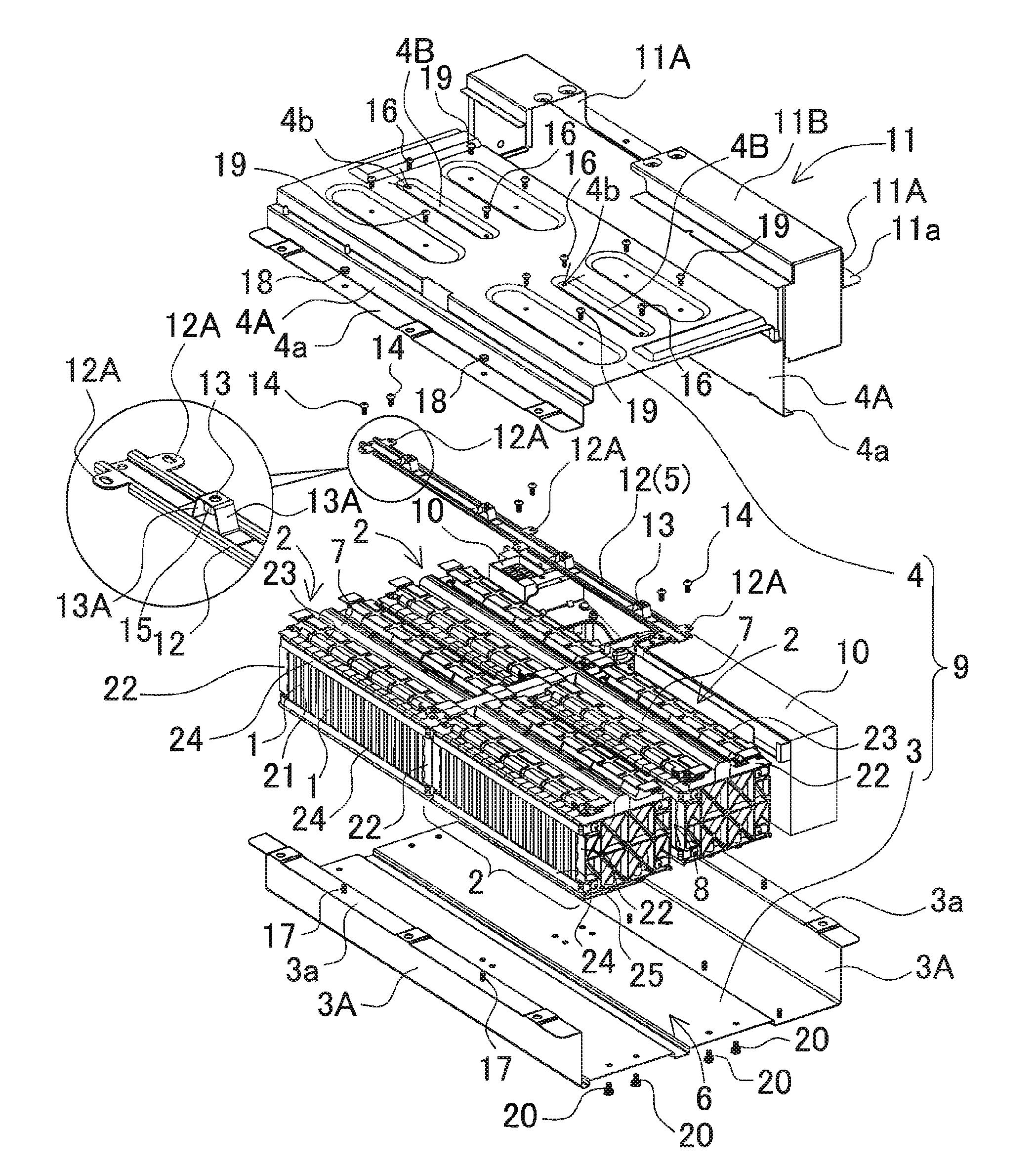
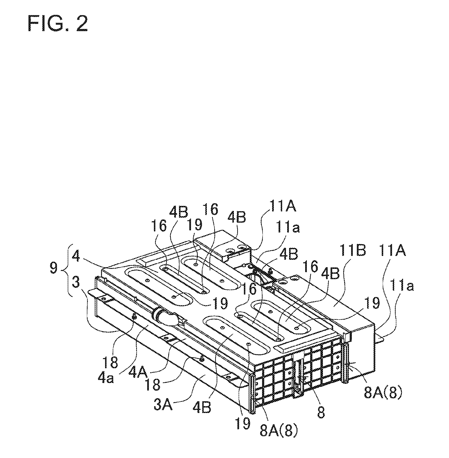
[0024]The following describes embodiments based on the figures. The car battery array shown in FIGS. 24 is provided with battery blocks 2 having a plurality of connected batteries 1; a first load-bearing plate 3 on which the battery blocks 2 are mounted; a second load-bearing plate 4 that covers the tops of the battery blocks 2 and attaches to both sides of the first load-bearing plate 3; and a reinforcing rod 5 disposed between, and connected to the second load-bearing plate 4 and the battery blocks 2 to connect the second load-bearing plate 4 to the battery blocks 2.

(Battery Blocks)

[0025]A battery block 2 has a plurality of battery cells 1 disposed in a stacked fashion via separators 21 with both ends of the stack sandwiched between endplates 22. A battery block 2 has a plurality of battery cells 1 disposed next to each other and electrode terminals (not illustrated) of adjacent battery cells 1 are connected together. Electrode terminals of adjacent battery cells 1 are stacked tog...

second embodiment

[0044]The car battery array shown in FIGS. 5 and 6 has a first load-bearing plate 33 and second load-bearing plate 34 that are trough-shaped metal plates with the same width. The first load-bearing plate 33 and second load-bearing plate 34 are connected together at side-walls 33A, 34A on both sides to form an external case 39 provided with a battery block 32 storage compartment 36. Attachment edges of the side-walls 33A, 34A are provided with outwardly bent flanges 33a, 34a. Flanges 33a, 34a are connected by screws (not illustrated) that pass through the flanges 33a, 34a and are held by nuts (not illustrated), or are attached by rivets that pass through the flanges 33a, 34a to join the first load-bearing plate 33 and the second load-bearing plate 34. In the same manner as the battery array of FIG. 3, the external case 39 houses two rows of two battery blocks 32 each arranged in straight lines to hold a total of four battery blocks 32. A cooling duct 38 is established between the two...


PUM


Abstract

The car battery array is provided with battery blocks 2 having a plurality of connected batteries 1, a first load-bearing plate 3 on top of which the battery blocks 2 are mounted, a second load-bearing plate 4 attached on both sides to the first load-bearing plate and covering the tops of the battery blocks 2, and a reinforcing rod 5 that connects with the second load-bearing plate 4 and the battery blocks 2 to attach the second load-bearing plate 4 to the battery blocks 2. Battery blocks 2 are disposed in a battery compartment 6 established inside the first load-bearing plate 3 and second load-bearing plate 4, which are joined together on both sides. The battery blocks 2 are mounted on top of the first load-bearing plate 3 and connected to the second load-bearing plate 4 via the reinforcing rod 5 to support the battery block 2 load with the first load-bearing plate 3 and the second load-bearing plate 4.

Description

BACKGROUND OF THE INVENTION[0001]1. Field of the Invention[0002]The present invention relates to a car battery array carried on-board an automobile to supply power to the car driving motor.[0003]2. Description of the Related Art[0004]A car battery array has many individual battery cells connected in series to raise the output voltage. The purpose is to supply a large amount of power to the driving motor. This type of battery array is provided with many high capacity battery cells resulting in a large overall weight. Individual battery cells are housed in an external case and carried on-board the automobile. A battery array with this type of structure is described, for example, in Japanese Laid-Open Patent Publication No. JP 2008-53149 A.[0005]FIG. 1 shows the battery array of JP 2008-53149 A. This battery array has many battery cells 91 stacked together and housed in an external case 99. The external case 99 has a lower frame plate 93 and an upper cover plate 94. The cover plate 94 ...

Claims


Application Information

Patent Timeline
IPC IPC(8): B60R16/04H01M10/60H01M10/613H01M10/625H01M10/647H01M10/653H01M10/6557H01M10/6563H01M10/6566H01M10/658H01M50/209H01M50/262H01M50/264H01M50/271
CPCH01M2/1077H01M10/5004H01M10/5057H01M10/5032H01M10/5016H01M10/625H01M10/647H01M10/6556H01M10/613Y02E60/10H01M50/209H01M50/264H01M50/271H01M50/262H01M50/50B60L50/50
Inventor OKADA, WATARU
Owner SANYO ELECTRIC CO LTD
Why Eureka
Try Eureka