Eureka AIR delivers breakthrough ideas for toughest innovation challenges, trusted by R&D personnel around the world.

Source driving circuit, displayer and control method thereof

Inactive Publication Date: 2010-01-07
CHUNGHWA PICTURE TUBES LTD
View PDF5 Cites 0 Cited by
  • Summary
  • Abstract
  • Description
  • Claims
  • Application Information

AI Technical Summary

Benefits of technology

[0008]The present invention provides a source driving circuit which may reduce ripple effects.
[0009]In addition, the present invention provides a driving circuit and method thereof for a display panel which may reduce power consumption when driving a display panel.
[0015]Each of the latches outputs the received data signals at different time intervals. Therefore, the power consumption as well as the ripple effects generated at the time of driving the display panel may be effectively reduced.

Problems solved by technology

The power consumption is considerably large.
In addition, large ripples are generated at both the power terminal and the ground terminal of the source driving circuit 110, resulting in errors of judgment in the circuit logic and even other status errors of the control signals.

Method used


Image

  • Source driving circuit, displayer and control method thereof
  • Source driving circuit, displayer and control method thereof
  • Source driving circuit, displayer and control method thereof

Examples


Embodiment Construction

[0024]The following description illustrates the elements of the present invention accompanied with the figures in detail. Persons of ordinary skill in the art should know that the term “couple” in the descriptions below means that two objects are connected directly, through at least one element such as a resistor, a capacitor, or a conductive line, or through a signal transmission, which is not limited by the present invention herein and will not be illustrated unless specifically required.

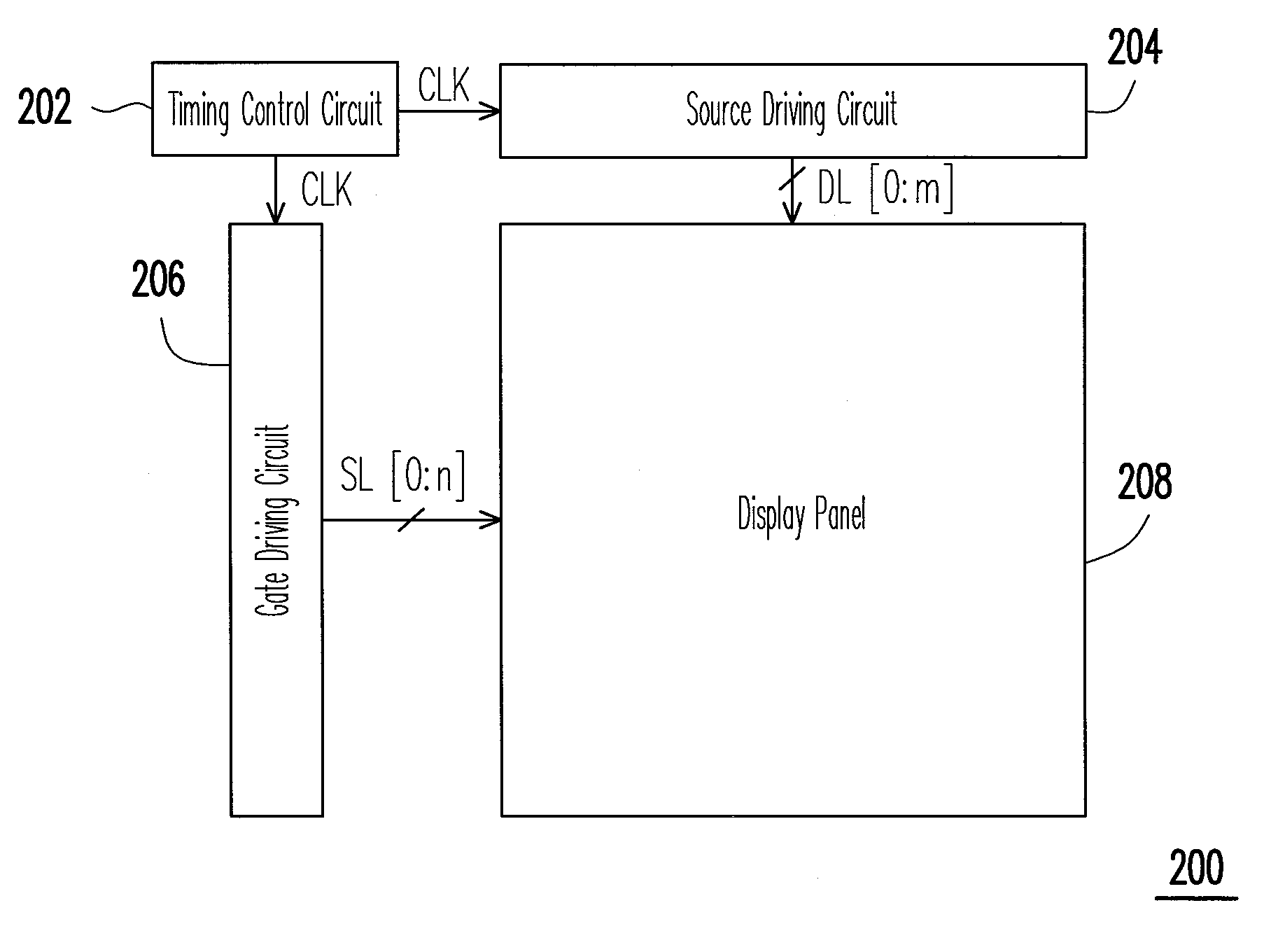
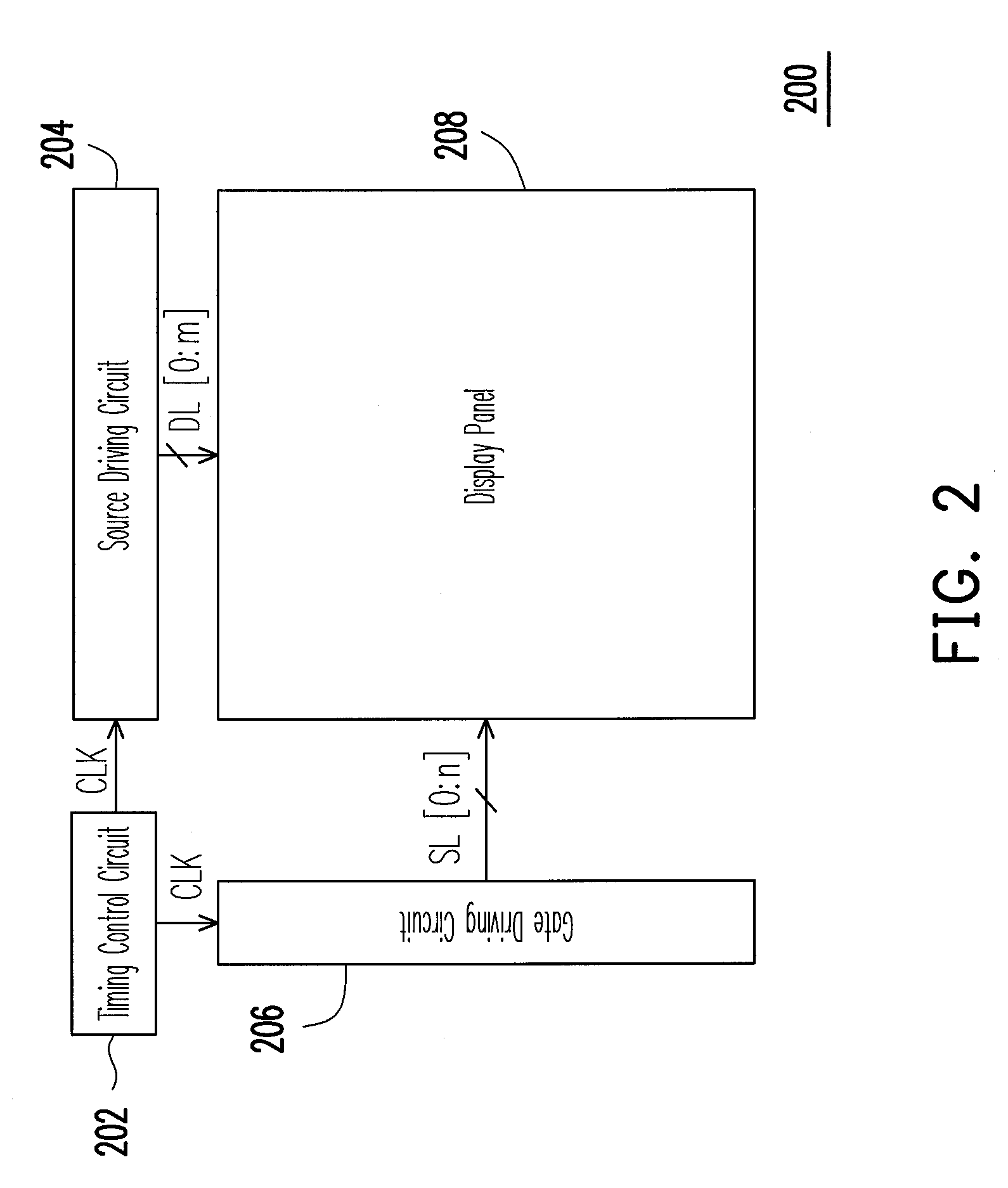
[0025]FIG. 2 is an internal block diagram of a displayer according to one embodiment of the present invention. Referring to FIG. 2, a displayer 200 may comprise a timing control circuit 202, a source driving circuit 204, a gate driving circuit 206, and a display panel 208. In the present embodiment, the display panel 208 may be an LCD panel, for example, and may be coupled to the source driving circuit 204 through m data lines DL and to the gate driving circuit 206 through n scan lines SL, wherein...


PUM


Abstract

A source driving circuit is suitable for a display panel. The source driving circuit of the present invention has a plurality of latches and a plurality of output buffers. Each of the latches is used for respectively receiving a data signal. In addition, all of the latches output the corresponding data signals at different time intervals according to a data output signal. After all of the latches have output the data signals to the corresponding output buffers, all output buffers transmit the data signals to the display panel synchronously.

Description

CROSS-REFERENCE TO RELATED APPLICATION[0001]This application claims the priority benefit of Taiwan application serial no. 97125594, filed Jul. 7, 2008. The entirety of the above-mentioned patent application is hereby incorporated by reference herein and made a part of specification.BACKGROUND OF THE INVENTION[0002]1. Field of the Invention[0003]The present invention relates to a source driving technology of a display panel and more particularly, to a source driving technology of a display panel having non-synchronous operations.[0004]2. Description of Related Art[0005]FIG. 1 illustrates a block diagram of a conventional source driving circuit. Referring to FIG. 1, in general, a source driving circuit 110 is used to drive a display panel 140. The conventional source driving circuit 110 comprises a plurality of latches 112, 114, . . . , 11n, respectively used to receive a plurality of data signals DS and transmit the received data signals to corresponding output buffers 122, 124, . . ...

Claims


Application Information

Patent Timeline
IPC IPC(8): G09G5/00
CPCG09G3/3674G09G2310/06G09G2310/02G09G3/3685
Inventor LIAN, WEI-JHIHSHIEH, YA-WEN
Owner CHUNGHWA PICTURE TUBES LTD
Why Eureka
Eureka Blog
Learn More