
USB receptacle for use with a powered receptacle or a rechargable flashlight having a powered receptacle

a technology of recharging flashlights and receptacles, which is applied in the direction of electric lighting with batteries, coupling device connections, lighting and heating apparatus, etc. it can solve the problems of not all electronic devices are compatible with the positive and negative, and the danger of a driver who should be concentrated on the road, etc., to achieve the effect of keeping the battery life of various devices and being easy to carry around

Inactive Publication Date: 2010-01-07
ARNOLD III VAUGHN R
View PDF26 Cites 23 Cited by
  • Summary
  • Abstract
  • Description
  • Claims
  • Application Information

AI Technical Summary

Benefits of technology

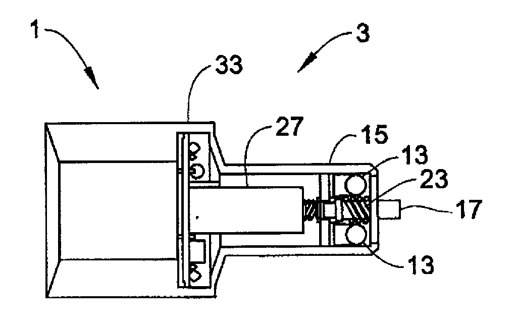
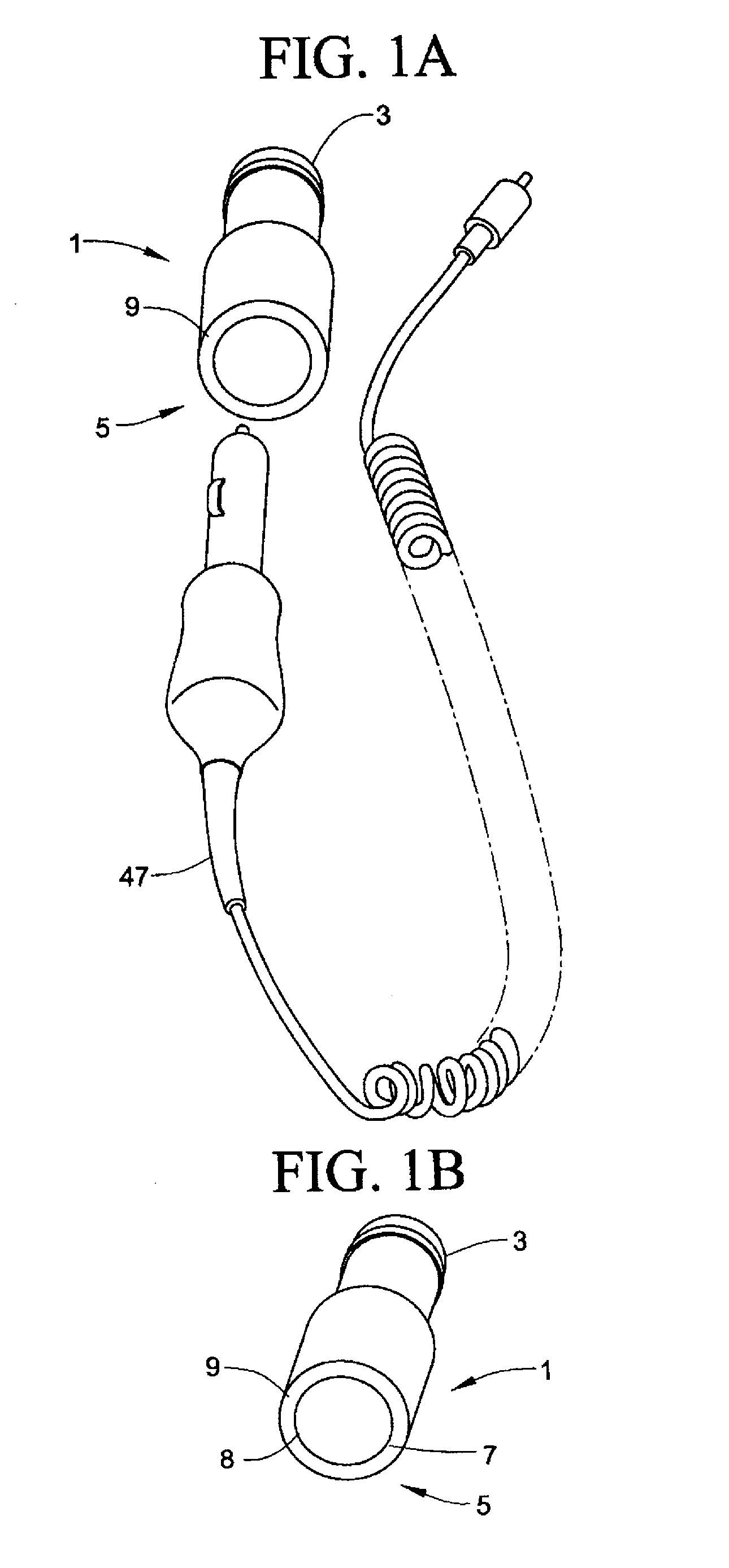
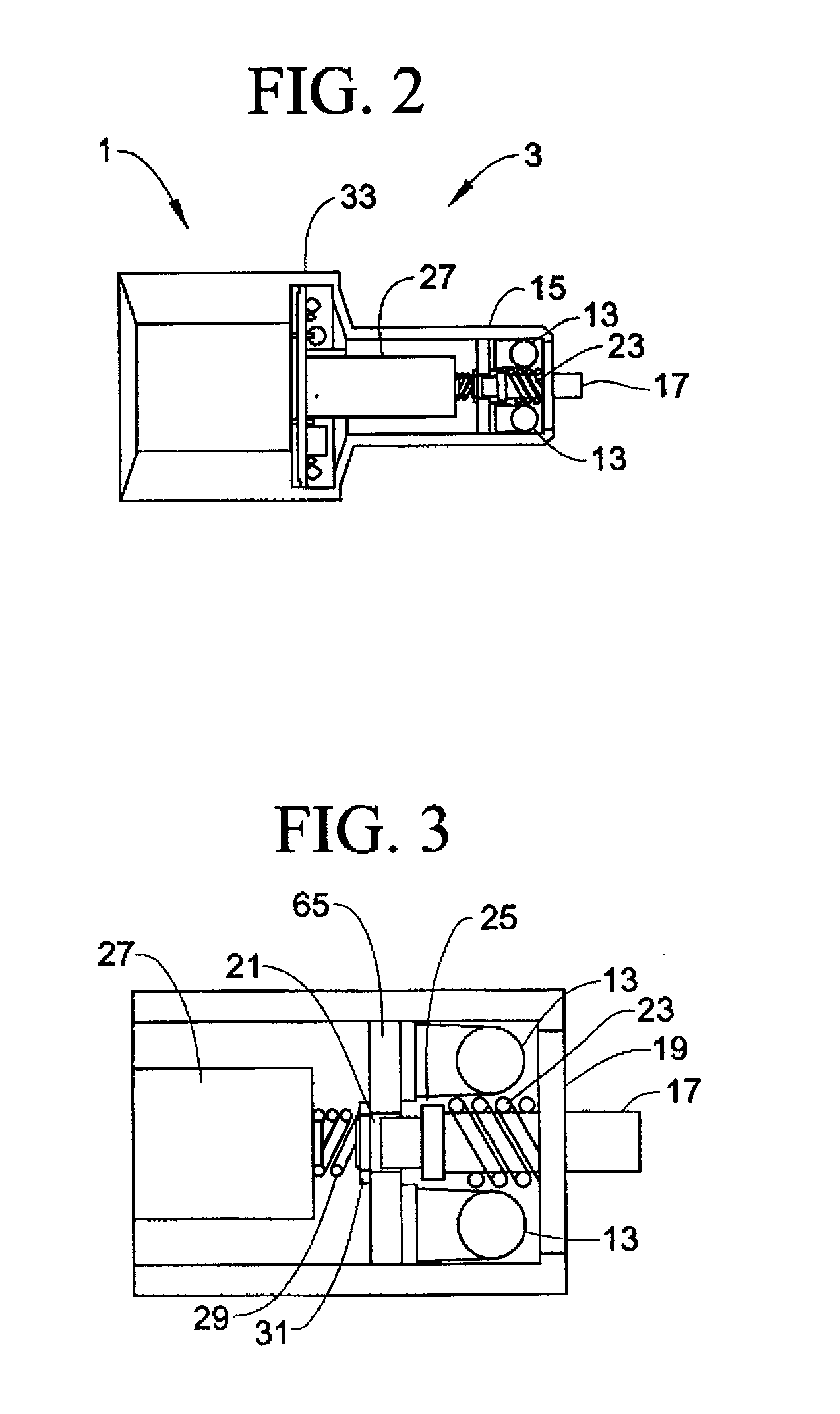
[0036]As a consequence of these aforementioned problems, it is an objective of the present invention to provide a USB mini port that can be inserted into a conventional cigarette lighter receptacle so as keep battery life of various devices charged. The USB mini port can be used independently or in combination with a plug-in rechargeable flashlight of the instant invention. The plug-in rechargeable flashlight may be inserted into a conventional cigarette lighter / power point receptacle found in an automobile, airplane, boat or other vehicle. The flashlight can be charged from a range of 1.5 volts DC to 32 volts DC and has light emitting diodes as the primary light source using a pass through receptacle that allows insertion of the USB mini plug. The primary light source is located on the end of the flashlight that plugs into the cigarette / power point receptacle making it easy to holster in the dark, as well as assure that accidental operation will not occur, such as when the device is used in an airplane cockpit. When the flashlight is plugged into the receptacle the primary light source is extinguished. The flashlight is also provided with an electrical output connection at the end of the flashlight opposite the primary light source. The electrical connection is powered when the flashlight is in the recharging position and off when the flashlight is removed from the cigarette lighter / power point receptacle. The electrical connection can power an the USB mini plug while simultaneously recharging the flashlight battery.
[0037]It is a objective of the instant invention to provide a rechargeable flashlight that is compact in size, reliable, easy to install, easy to use, attractive in appearance and includes a receptacle for receipt of the USB mini plug of the instant invention.
[0038]It is a further objective of the instant invention to provide a USB mini plug that is compact in size, reliable, easy to install, easy to use, and provides power management for other electrical devices commonly carried in a vehicle.
[0040]It is yet still another objective of the instant invention to provide a compact flashlight that can be plugged into a cigarette lighter receptacle to maintain the battery power at its peak efficiency.
[0043]Yet another objective is to provide the operators of movable vehicles, such as airplanes, with a readily accessible flashlight that is maintained at its peak charge and further allows the pass through of power for other items, such as GPS units, without the need of power socket splitters.

Problems solved by technology

The disadvantages associated with U.S. Pat. Nos. 4,325,107, 4,224,658 and 2006 / 0274541 A1 is that the flashlight, which requires a cigarette lighter socket for recharging means, occupies the only port in the vicinity of the driver thus not allowing other devices which are more commonly used to be charged simultaneously.
However, not all electronic devices are compatible with the positive and negative leads extending from the universal connector.
In addition to switching between devices for charging purposes creates a hazard for a driver whom should be concentrated on the road.
The setback is low-life span for the internal batteries of the flashlight since the auxiliary electronic devices are drawing current directly from the internal batteries of the flashlight.
Furthermore, the charging means for the flashlight is not within the body of the flashlight, thus making the apparatus cumbersome for a user with limited space in a vehicle.
Using the adapter in conjunction with a rechargeable flashlight only requires the use of more equipment within a vehicle creating a bulky situation.
The use of a light diode renders the lamp insensitive to shock effects and contributes to the lifespan thereof.

Method used


Image

  • USB receptacle for use with a powered receptacle or a rechargable flashlight having a powered receptacle
  • USB receptacle for use with a powered receptacle or a rechargable flashlight having a powered receptacle
  • USB receptacle for use with a powered receptacle or a rechargable flashlight having a powered receptacle

Examples


Embodiment Construction

[0073]Detailed embodiments of the instant invention are disclosed herein, however, it is to be understood that the disclosed embodiments are merely exemplary of the invention, which may be embodied in various forms. Therefore, specific functional and structural details disclosed herein are not to be interpreted as limiting, but merely as a basis for the claims and as a representation basis for teaching one skilled in the art to variously employ the present invention in virtually any appropriately detailed structure.

[0074]Referring now to FIGS. 1-5, wherein like elements are numbered consistently throughout. The present invention is directed to the use of a rechargeable flashlight within an automobile. However, use within an automobile is only for a suggested use of the rechargeable flashlight; as the rechargeable flashlight is readily used in trucks, boats, airplanes, or any other transportation device that employs a cigarette type power output. FIG. 1A illustrates one preferred emb...


PUM


Abstract

A USB mini plug for use independently or in combination with a plug-in rechargeable flashlight. The USB mini plug may be inserted into a conventional cigarette lighter or battery power source receptacle found in an automobile, truck, airplane, boat or other vehicle. The flashlight has light emitting diodes as the primary light source located on the end of the flashlight which is insertable into the power receptacle concealing the light source. When the flashlight is plugged into the receptacle the primary light source is extinguished. The flashlight is further provided with an electrical output connection at the opposite end of the primary light source allowing the flashlight to serve as a replacement socket for the power receptacle consumed by the flashlight. The replacement socket provides an electrical connection for receipt of additional powered accessories, or limited in use to pre-selected items such as the USB mini port.

Description

PRIORITY CLAIM[0001]This is a divisional of U.S. patent application Ser. No. 12 / 104,933 claiming a priority date based on U.S. provisional Patent Application No. 60 / 946,580 filed Jun. 27, 2007, the contents of which are incorporated herein by reference.FIELD OF THE INVENTION[0002]The present invention relates to USB receptacles and, in particular, to a USB mini plug receptacle for use with a DC powered receptacle or for use in combination with a flashlight having a pass-through receptacle.BACKGROUND OF THE INVENTION[0003]USB ports are an industry standard for coupling most cell phones, MP3 players, GPS navigation systems, personal digital assistants (PDA's), laptop computers, and so forth. These devices are battery powered and require recharging. While such devices are commonly purchased with a battery charger for coupling to an AC source, the battery charger for a DC source is typically an option. DC battery chargers are commonly bulky and brand labeled making them expensive as the...

Claims


Application Information

Patent Timeline
Patent Type & Authority Applications(United States)
IPC IPC(8): F21L4/00H01R27/02
CPCF21L4/085
Inventor ARNOLD, III, VAUGHN R.
Owner ARNOLD III VAUGHN R
Learn More