Programming method for tire pressure monitor sensors

a technology of monitor sensor and programming method, which is applied in the field of tire pressure monitor sensor, can solve the problems of unnecessarily slow programming process, inability of tpms sensor to process low frequency (lf) data and transmit uhf at the same time, and long time taken to program tpms sensor, so as to maintain the security of the programming process

Inactive Publication Date: 2015-10-13
BARTEC USA
View PDF14 Cites 4 Cited by
  • Summary
  • Abstract
  • Description
  • Claims
  • Application Information

AI Technical Summary

Benefits of technology

[0008]For TPMS, it is not advisable to allow anyone to have the ability to reprogram the sensors, and so encryption of the programming process is used and the absence of unencrypted data helps maintain the security of the system. TPMS sensors may run their processing units at low speed in order to preserve battery life, and may also turn off parts of their circuitry that are not needed. For example, it may be that a TPMS sensor cannot both process low frequency (LF) data and transmit UHF at the same time. One method of programming a sensor using LF is to send data in frames, and for the sensor to validate the data, and then signal using UHF to indicate that the frame was received correctly, before the programming tool sends more LF data. This is a fairly slow process, so improved quicker processes are desired.
[0011]The present disclosure provides a method of programming a tire pressure monitor sensor to solve the above-described problem. In particular, the present disclosure utilizes a programming tool that transmits LF data frames to the TPMS sensor that includes a cyclic redundancy check (CRC) code with each data frame. The starting point for the subsequent data frame will then start with the CRC code received from the previous frame and will end with a new CRC code. Accordingly, the CRC code received from the previous frame will be used to ensure that the next data frame matches that CRC code as the starting point for that frame. This will ensure that the data frames cannot get out of sequence and will allow the ability to quickly identify where the data frames have gone out of sync and allow the programming tool to quickly react.
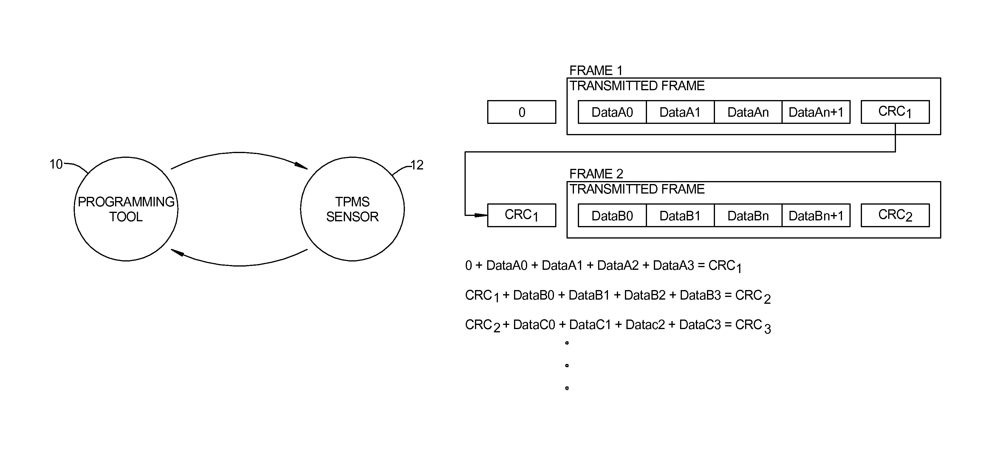
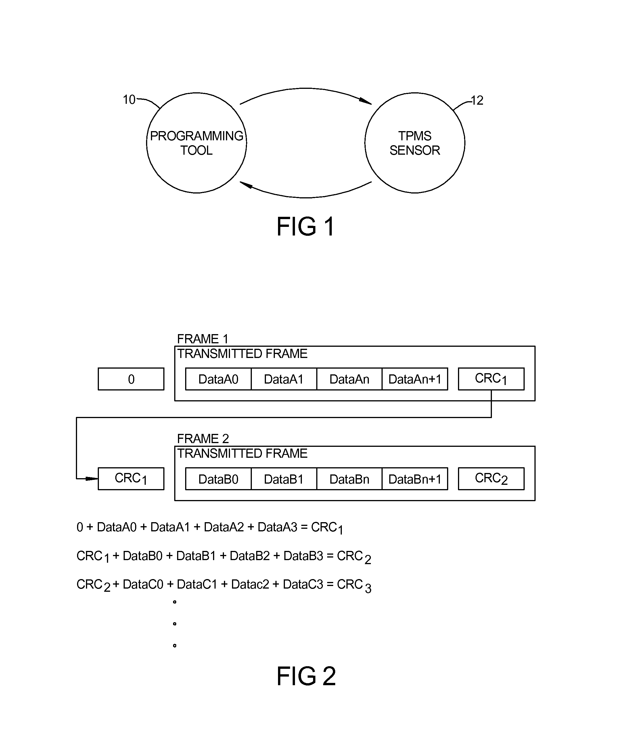
[0021]With reference to FIG. 1, a programming tool 10 is shown that is capable of transmitting data to a TPMS sensor 12 for programming the sensor. The sensor 12 is capable of providing signals back to the programming tool 10 that allow the sensor 12 to indicate whether the data was received correctly or incorrectly as will be described in detail herein. With reference to FIG. 1, the programming data sent from the programming tool 10 to the TPMS sensor 12 is in the form of low frequency data frames which includes the programming data, representative by the labels Data A0, Data A1, Data An, and Data An+1 for exemplary purposes. Each data frame is also provided with a CRC, such as the CRC1 provided with the frame 1 data. The valve of CRC1 is equal to the sum of 0+Data A0+Data A1+Data A2+Data A3 which can be confirmed by the receiving TPMS sensor. In a subsequent data frame, the transmitted data frame will be begin with the previous CRC, such as CRC1 so that the sensor can confirm that the CRC code of the subsequent frame matches the CRC code provided in the previous frame prior to accepting the data that is received in that frame 2. The frame 2 would include additional programming data, representative by the labels Data B0, Data B1, Data Bn, and Data Bn+1 which is then accompanied by a second CRC code, for example CRC2 which will then be utilized in the subsequent frame 3 as a confirmation that the proper data frame is being received. In other words, the present disclosure provides for the feedback of a previous CRC into the calculation of the subsequent frame such that unless the previous frame was received correctly, the subsequent frame will fail the validation check and will not proceed until the missing frame is retransmitted. In the illustrative example, the receiving TPMS sensor will confirm that CRC2 is equal to the sum of CRC1+Data B0+Data B1+Data B2+Data B3. In such a case that the received CRC2 value does not match the calculated CRC2 value, the TPMS sensor will notify the transmitting programming tool that there was a CRC error at a given point in the process and the programming tool will resume from the point of failure. This will ensure that the transmission of the data frames can never get out of sequence, and it will also allow the TPMS sensor and programming tool to quickly identify where the data transmission has gone out of sync and react. This is important in the relatively long time taken to program a TPMS sensor. It is not beneficial or efficient to wait until the full programming time has expired before declaring a failure, if the process could be failed or corrected at a much earlier stage. This method also has the advantage of no plain text transfer, which helps maintain the security of the programming process.

Problems solved by technology

In a typical communications protocol that does not rely upon the acknowledgement of each individual frame transmitted, or the inclusion of a sequence byte in the data (which is a security vulnerability), it is possible that the receiver may fail to receive such a frame and will ultimately fail to program correctly.
For example, it may be that a TPMS sensor cannot both process low frequency (LF) data and transmit UHF at the same time.
However, this would result in an unnecessarily slow programming process in the usual case where the data is transferred without corruption.

Method used


Image

  • Programming method for tire pressure monitor sensors
  • Programming method for tire pressure monitor sensors

Examples


Embodiment Construction

[0017]Example embodiments will now be described more fully with reference to the accompanying drawings.

[0018]Example embodiments are provided so that this disclosure will be thorough, and will fully convey the scope to those who are skilled in the art. Numerous specific details are set forth such as examples of specific components, devices, and methods, to provide a thorough understanding of embodiments of the present disclosure. It will be apparent to those skilled in the art that specific details need not be employed, that example embodiments may be embodied in many different forms and that neither should be construed to limit the scope of the disclosure. In some example embodiments, well-known processes, well-known device structures, and well-known technologies are not described in detail.

[0019]The terminology used herein is for the purpose of describing particular example embodiments only and is not intended to be limiting. As used herein, the singular forms “a,”“an,” and “the” ...


PUM


Abstract

A method of programming a tire pressure monitor sensor utilizes a programming tool that transmits LF data frames to the TPMS sensor that includes a cyclic redundancy check (CRC) code with each data frame. The starting point for the subsequent data frame will then start with the CRC code received from the previous frame and will end with a new CRC code. Accordingly, the CRC code received from the previous frame will be used to ensure that the next data frame matches that CRC code as the starting point for that frame. This will ensure that the data frames cannot get out of sequence and will allow the ability to quickly identify where the data frames have gone out of sync and allow the programming tool to quickly react.

Description

CROSS-REFERENCE TO RELATED APPLICATIONS[0001]This application claims the benefit of U.S. Provisional Application No. 61 / 720,434, filed on Oct. 31, 2012. The entire disclosure of the above application is incorporated herein by reference.FIELD[0002]The present disclosure relates to tire pressure monitor sensors, and more particularly, to a system and method for programming tire pressure monitor sensors.BACKGROUND AND SUMMARY[0003]This section provides background information related to the present disclosure which is not necessarily prior art.[0004]Tire pressure monitoring systems have been developed, including a tire pressure monitor sensor (TPMS) that is mounted to each wheel for sending signals to a central receiving unit aboard a vehicle for providing information regarding the tire pressure and temperature. Each of the tire pressure monitor sensors includes a respective radio frequency (RF) transmitter that transmits an RF signal in response to the receipt of an LF (low frequency) ...

Claims


Application Information

Patent Timeline
Patent Type & Authority Patents(United States)
IPC IPC(8): B60C23/04H03M13/09H03M13/33
CPCH03M13/09B60C23/0462H03M13/333B60C23/0479B60C23/0481B60C23/0471
Inventor GAVIN, MICHAEL JOHNWEBB, COLINASCHAM, STEVEBEAL, CHARLES W.
Owner BARTEC USA
Why Eureka
Try Eureka