Porous implant with non-porous threads

a non-porous, threadless technology, applied in dental implants, dental surgery, medical science, etc., can solve the problems of not providing sufficient strength for threads on screw-types, only forming near the surface of bone growth,

Active Publication Date: 2010-01-07
ZIMMER DENTAL INC
View PDF17 Cites 43 Cited by
  • Summary
  • Abstract
  • Description
  • Claims
  • Application Information

AI Technical Summary

Problems solved by technology

Providing a porous material only on the surface of the implant, however, results in bone growth only near the surface of the implant.
S...

Method used


Image

  • Porous implant with non-porous threads
  • Porous implant with non-porous threads
  • Porous implant with non-porous threads

Examples


Embodiment Construction

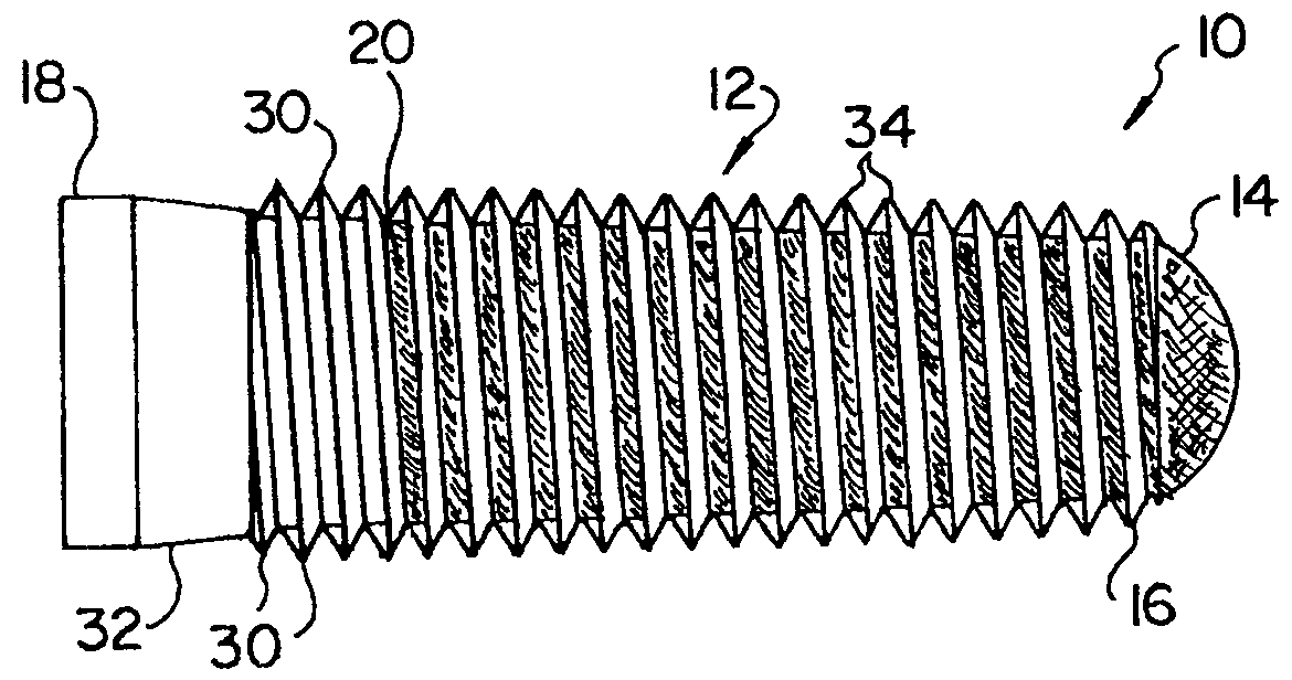
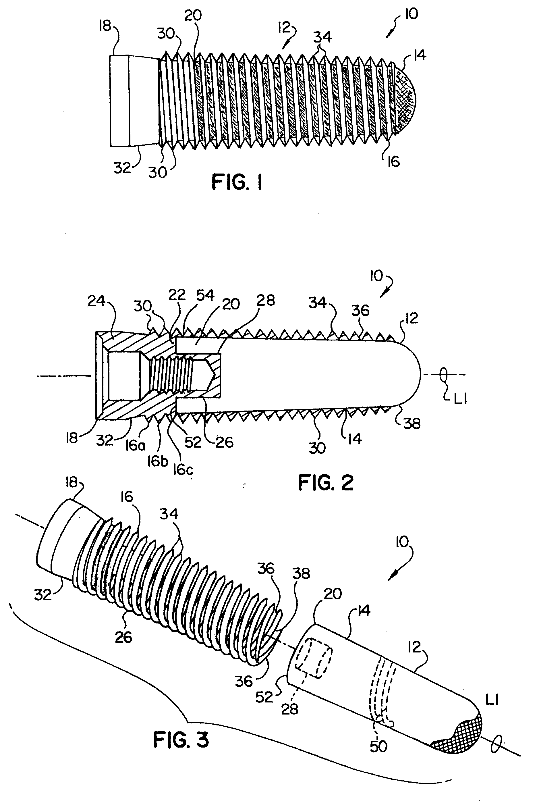
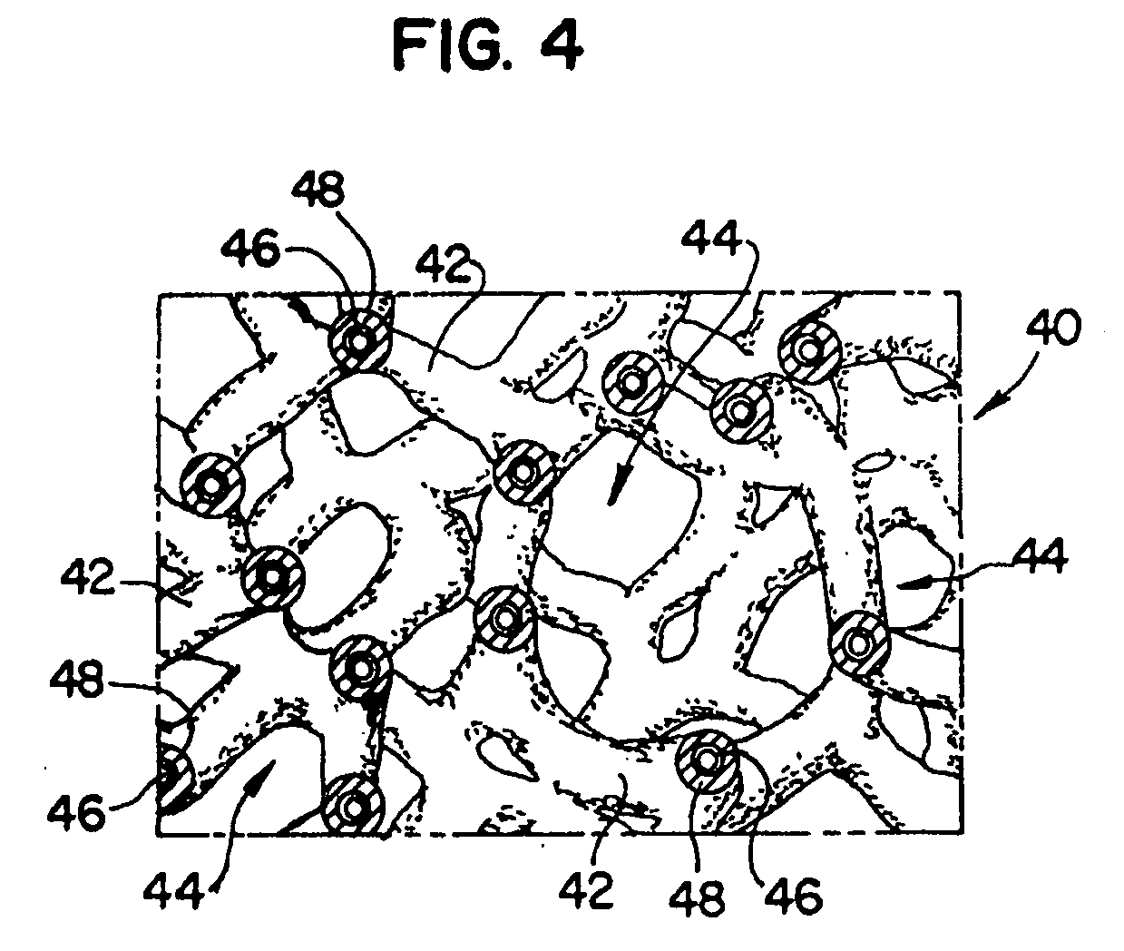
[0013]Referring to FIGS. 1-3, an implant 10 may be used to anchor prosthetic devices to bone. In one form, implant 10 is a dental implant for anchoring an abutment or other dental prosthesis to a jaw bone. The implant 10 generally defines a longitudinal axis L1 (shown in FIG. 2) and includes a shaft 12 made of a porous material for improving osseointegration onto the implant 10 as explained in greater detail below. The shaft 12 has an exterior surface 14 and at least one non-porous thread 16 winding around, and engaging, the exterior surface 14, and extending outwardly from the exterior surface 14 for engaging bone. While the illustrated shaft 12 is substantially porous, shaft 12 could have a non-porous, axially extending core. Such a core could be made of titanium, ceramic or other non-porous material.

[0014]Implant 10 includes a non-porous head portion 18 located at a coronal end portion 20 of the shaft 12. The non-porous head portion 18 is made of a suitable biocompatible material...


PUM


Abstract

An implant which includes a shaft made of a first material and having an exterior surface, and at least one thread made of a second material different from the first material, engaging the exterior surface, and extending outwardly from the exterior surface for engaging bone. After implantation of the implant, bone tissue may osseointegrate into the porous shaft to anchor the implant within the surrounding bone. The first material may be a porous metal and include tantalum while the second material is non-porous.

Description

BACKGROUND OF THE INVENTION[0001]1. Field of the Invention[0002]The present invention relates to bone implants and, in particular, to a threaded dental implant with improved osseointegration.[0003]2. Description of the Related Art[0004]Dental implants are commonly used as anchoring members for dental restorations to provide prosthetic teeth at one or more edentulous sites in a patient's dentition at which the patient's original teeth have been lost or damaged. Typically, known implant systems include a dental implant made from a suitable biocompatible material, such as titanium. The dental implant is typically threaded into a bore which is drilled into the patient's mandible or maxilla at the edentulous site. The implant provides an anchoring member for a dental abutment, which in turn provides an interface between the implant and a dental restoration. The restoration is typically a porcelain crown fashioned according to known methods.[0005]Many current dental implant surgeries are ...

Claims


Application Information

Patent Timeline
IPC IPC(8): A61C8/00
CPCA61C8/0012A61C8/0013A61C8/0022A61C8/0018A61C8/0016A61C8/0042
Inventor SALVI, JOSEPH A.ZAMANI, SHAHRAMESFAHANI, MOJTABA
Owner ZIMMER DENTAL INC
Why Eureka
Try Eureka