
Processing of Biosignal

a biosignal and processing technology, applied in the field of biosignal processing, can solve the problems of biosignal measurement, such as electrocardiographic or electromyographic measurement, prone to failure, poor signal quality

Active Publication Date: 2010-01-07
POLAR ELECTRO
View PDF3 Cites 12 Cited by
  • Summary
  • Abstract
  • Description
  • Claims
  • Application Information

AI Technical Summary

Problems solved by technology

Biosignal measurements, such as electrocardiographic or electromyographic measurements, are prone to failure and poor signal quality due to changing measurement conditions.

Method used


Image

  • Processing of Biosignal
  • Processing of Biosignal
  • Processing of Biosignal

Examples


Embodiment Construction

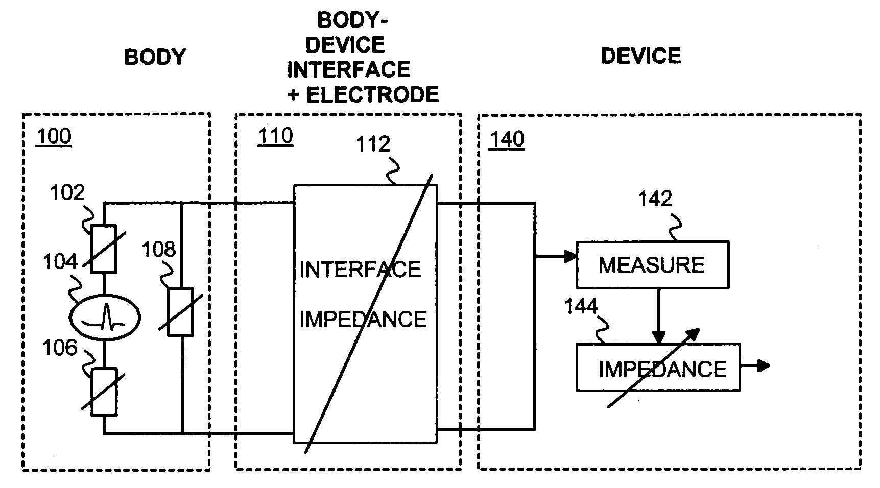
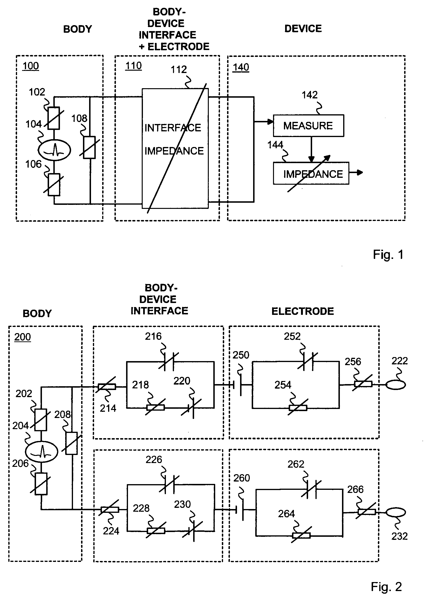
[0015]FIG. 1 shows an embodiment of an arrangement to which the invention may be applied. In FIG. 1, a biosignal is measured from a living object 100 with a measuring device 140 via a measuring interface 110. The living object may be a human or an animal body. The measuring device may be a performance monitor or an exercising device, for instance. The interface may in practise include the skin of the object and one or several measuring electrodes of the device. The biosignal may be an electric signal induced by the body, such as an electrocardiographic (ECG) or an electromyographic (EMG) signal.

[0016]Thus, in an embodiment, the source of the biosignal is the heart 104 of the object. The heart 104, the rest of the body, and the interface 110 between the body 100 and the measuring device 140 constitute a closed electrical circuit.

[0017]The different elements of the electrical circuit cause attenuation to the signal. In this context, the body has constant impedance for the same living ...


PUM


Abstract

An apparatus for use in connection with biosignal measurement from the skin of a living object, comprising means for applying a test input impedance to the biosignal measurement, means for determining a response of a biosignal characteristics to the test input impedance, and means for setting a usage input impedance on the basis of the response.

Description

CROSS-REFERENCE TO RELATED APPLICATION[0001]This application claims priority based on Finnish Patent Application No. 20085693, filed Jul. 3, 2008, which is incorporated herein by reference.BACKGROUND[0002]1. Field[0003]The present invention relates to processing of a biosignal measured from a living object.[0004]2. Description of the Related Art[0005]Biosignal measurements, such as electrocardiographic or electromyographic measurements, are prone to failure and poor signal quality due to changing measurement conditions. The changing measurement conditions primarily arise from difference in object characteristics, such as tissue conductivity, and dynamics in the conductivity between tissue-electrode interface. Therefore, it is desirable to consider improvements in biosignal measurements.SUMMARY[0006]In an aspect, there is provided an apparatus for use in connection with biosignal measurement from the skin of a living object. The apparatus comprises means for applying a test input imp...

Claims


Application Information

Patent Timeline
Patent Type & Authority Applications(United States)
IPC IPC(8): A61B5/0402A61B5/053A61B5/308G01R27/08
CPCA61B5/04288A61B5/6843A61B5/0531A63B2230/06A63B22/0056A63B22/02A63B2230/60A61B5/304
Inventor RYTKY, PEKKA
Owner POLAR ELECTRO
Learn More