Method for measuring viscosity and/or elasticity of liquid

a technology applied in the field of viscosity and/or elasticity measurement of liquids, can solve the problems of poor measurement accuracy, inability to measure both the viscosity value and the elasticity value that are required for determining the dynamic characteristics of liquids, and inability to accurately measure the viscosity value of high viscosity liquids to be tested. achieve the effect of high viscosity, accurate measurement, and accurate determination of visco

Inactive Publication Date: 2010-01-14
SEKONIC CORP
View PDF5 Cites 57 Cited by
  • Summary
  • Abstract
  • Description
  • Claims
  • Application Information

AI Technical Summary

Benefits of technology

[0012]By the measurement method according to the present invention, the real part and the imaginary part of impedance are determined with the use of the resonance frequency (f0), the low frequency value (f1), and the high frequency value (f2). Even if the liquid to be tested is a high viscosity liquid, the viscoelasticity of the liquid can be accurately measured, and the viscosity or elasticity can be accurately determined from the viscoelasticity.

Problems solved by technology

As a result, the viscosity value of a high viscosity liquid to be tested cannot be measured with accuracy, and it is impossible to measure both the viscosity value and the elasticity value that are required for determining the dynamic characteristics of the liquid.
By a measurement method involving determination of the impedance of a liquid from the frequency and the amplitude attributable to the inherent viscoelasticity of the liquid like the method disclosed in Japanese Patent Publication No. 3348162, or by a measurement method involving the real part of the impedance as the reciprocal of a sensor output voltage proportional to the amplitude, the measurement accuracy becomes poorer, since the amplitude becomes smaller as the viscosity of the tested liquid becomes higher.

Method used


Image

  • Method for measuring viscosity and/or elasticity of liquid
  • Method for measuring viscosity and/or elasticity of liquid
  • Method for measuring viscosity and/or elasticity of liquid

Examples


Embodiment Construction

[0017]The following is a description of preferred embodiments of the present invention, with reference to FIGS. 1 through 4.

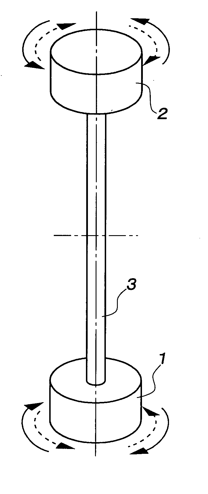
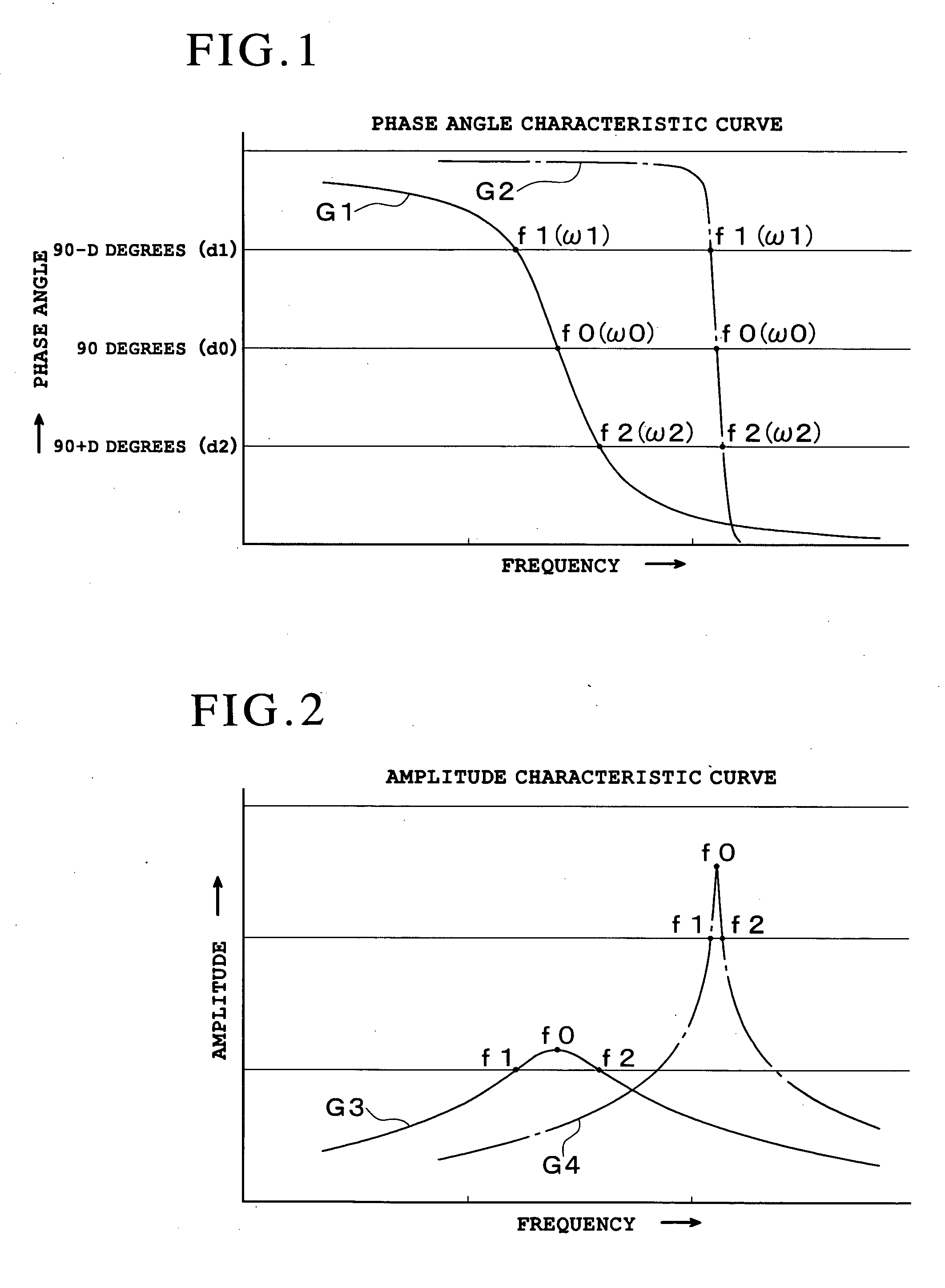
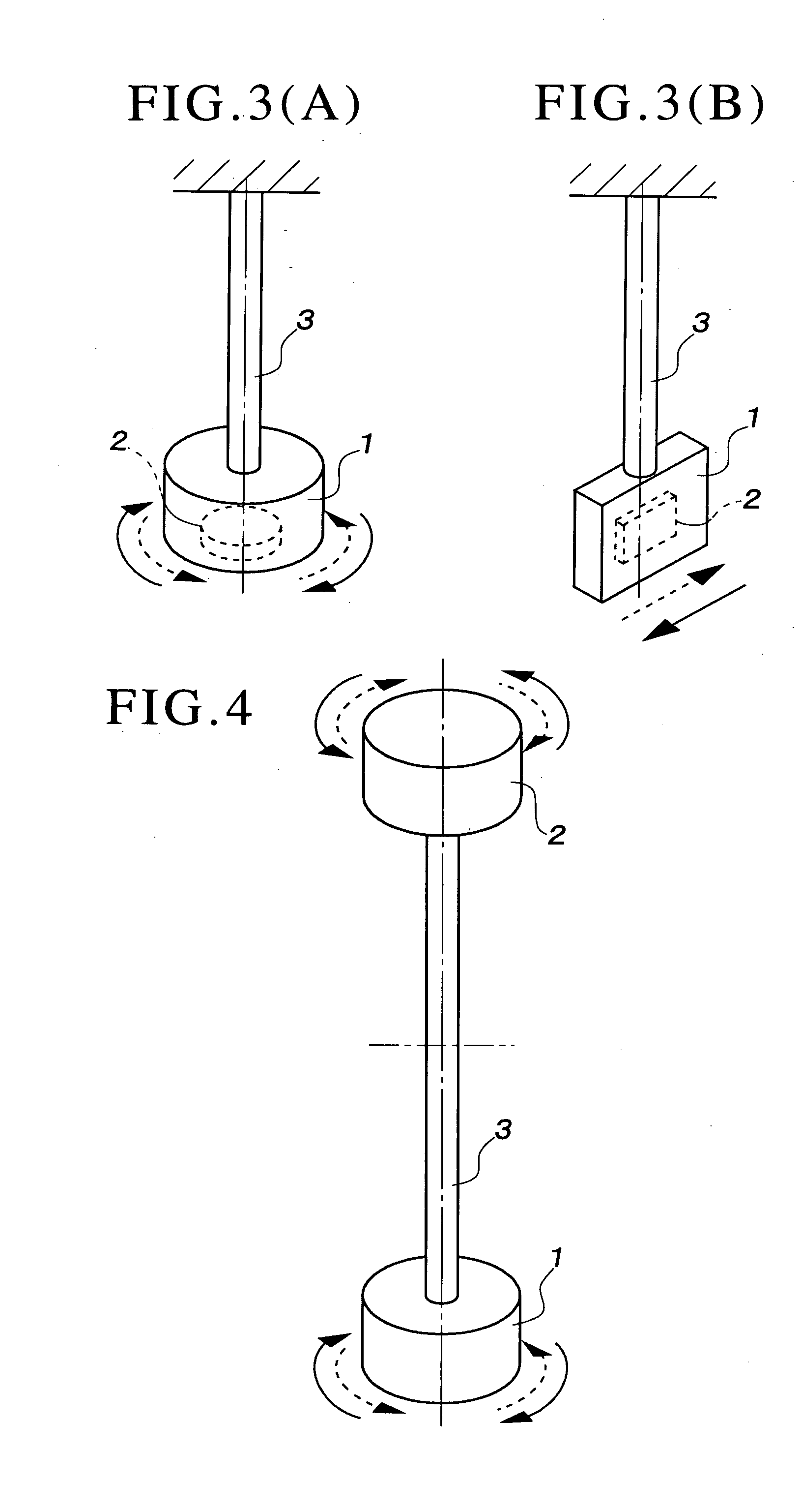
[0018]In FIG. 1, G1 is the characteristic curve of the delay angle of the amplitude with respect to the vibrational frequency of a liquid tester 1 that vibrates in a liquid to be tested, or the characteristic curve of the phase angle.

[0019]On the other hand, G2 is the characteristic curve of the delay angle of the amplitude with respect to the vibrational frequency observed when the liquid tester 1 is vibrated in the air, or the characteristic curve of the phase angle.

[0020]In FIG. 2, G3 is the characteristic curve of the amplitude with respect to the vibrational frequency of the liquid tester 1 that vibrates in the liquid to be tested.

[0021]On the other hand, G4 is the characteristic curve of the amplitude with respect to the vibrational frequency observed when the liquid tester 1 is vibrated in the air.

[0022]In FIG. 1, f0, f1, and f2 on the phase angle charac...


PUM

PropertyMeasurementUnit
phase anglesaaaaaaaaaa
angleaaaaaaaaaa
angleaaaaaaaaaa

Abstract

The present invention provides a method for measuring the viscosity and/or elasticity of a liquid by which accurate viscoelasticity measurement can be performed on a wide variety of liquids to be tested ranging from low viscosity liquids to high viscosity liquids, and viscosity and/or elasticity can be precisely determined from the viscoelasticity. This method includes: measuring three frequency values that are the resonance frequency value (f0) on the amplitude characteristic curve obtained through the vibration of the liquid tester 1 in the liquid being tested, a low frequency value lower (f1) than the resonance frequency value (f0) on the amplitude characteristic curve, and a high frequency value (f2) higher than the resonance frequency value (f0) on the amplitude characteristic curve; calculating the real part of the impedance of the liquid being tested, using the high frequency value (f2) and the low frequency value (f1); calculating the imaginary part of the impedance of the liquid being tested, using the resonance frequency value (f0); and calculating the viscosity value and/or the elasticity value of the liquid being tested from the real part and the imaginary part of the impedance.

Description

BACKGROUND OF THE INVENTION[0001]1. Field of the Invention[0002]The present invention relates to a method for measuring the viscosity and / or elasticity of a liquid by which the viscoelasticity of the liquid to be tested can be accurately measured, and the viscosity or elasticity can be accurately determined from the viscoelasticity.[0003]2. Description of the Related Art[0004]Japanese Patent Publication No. 4083621 discloses a method for measuring a viscosity value (viscosity). By this method, a vibrator (such as a piezoelectric device) is resonated in a liquid to be tested, and the viscosity value (the viscosity) of the liquid is measured from the difference between the resonance frequency and either a low frequency value (a half-value frequency f1) lower than the resonance frequency value or a high frequency value (a half-value frequency f2) higher than the resonance frequency value.[0005]Japanese Patent Publication No. 3348162 discloses a method for measuring the viscoelasticity ...

Claims


Application Information

Patent Timeline
Patent Type & Authority Applications(United States)
IPC IPC(8): G01N11/16
CPCG01N11/16G01N11/162
Inventor MIURA, SHINSUKE
Owner SEKONIC CORP
Why Eureka
Try Eureka