Reversible printing table

Inactive Publication Date: 2010-01-14
MATAN DIGITAL PRINTERS
View PDF3 Cites 17 Cited by
  • Summary
  • Abstract
  • Description
  • Claims
  • Application Information

AI Technical Summary

Benefits of technology

[0014]The present invention is directed to providing cost-effective and spa

Problems solved by technology

The wider the sheet, the greater the tendency for it to be warped or misaligned whilst being fed past the print head, and a great deal of effort has been expended in keeping the medium taut and flat.
Even a small deviation from the correct positioning results in noticeable printing defects.
However, the wider the material to be printed, the more difficult it is to maintain alignment between substrate and print-head.
Therefore, providing a single printer that is capable of accurate flat-bed and roll to roll printing, though desirable, is not easily achieved.
Moving from one printing mode to another in this manner is likely to be time consuming.
Furthermore, since the print head may be moved with respect to the substrate to be printed in three directions, accurate, repeatable alignment and moving from one printing type to the other is not easy.
Because two printing tables are used, both require calibrating to attain planarity in a parallel plane to the movement of the print head, and this planarity is not easily achieved since the printing tables have a tendency to warp.
The table used is a wide table suitable for flat-bed printing, which, when used for roll-to-roll printing, is inherently unsuitable as the distance between the rollers is large, and the flexible substrate to be printed is likely to assume a wavy surface which adversely affects the resolution of the printing thereon.
The controller for controlling the amount of error and the need for compensation thereof indicate the problems in obtaining accurate positioning where the bridgehead moves relative to the support area, the support area moves relative to the material to be printed, and the material to be printed is fed as well.
It is difficult to keep a flexible material which is passed over a planar printing table adequately tensioned by dual mode printers of the prior art.
Therefore prior art systems tend to have limited performance in one or other of the printing modes.

Method used


Image

  • Reversible printing table
  • Reversible printing table
  • Reversible printing table

Examples


first embodiment

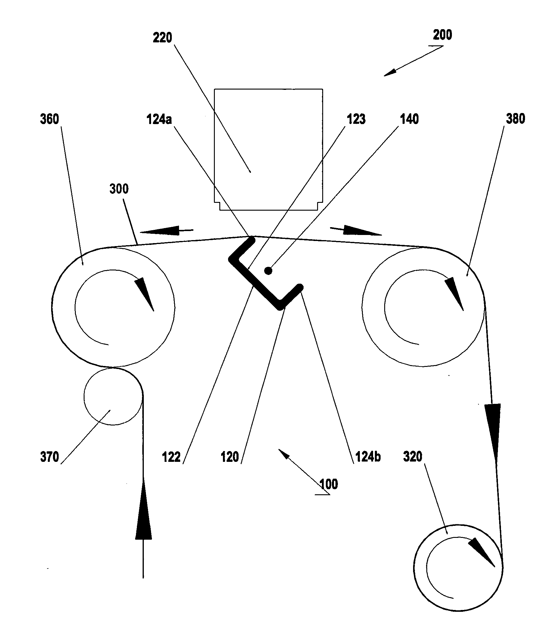
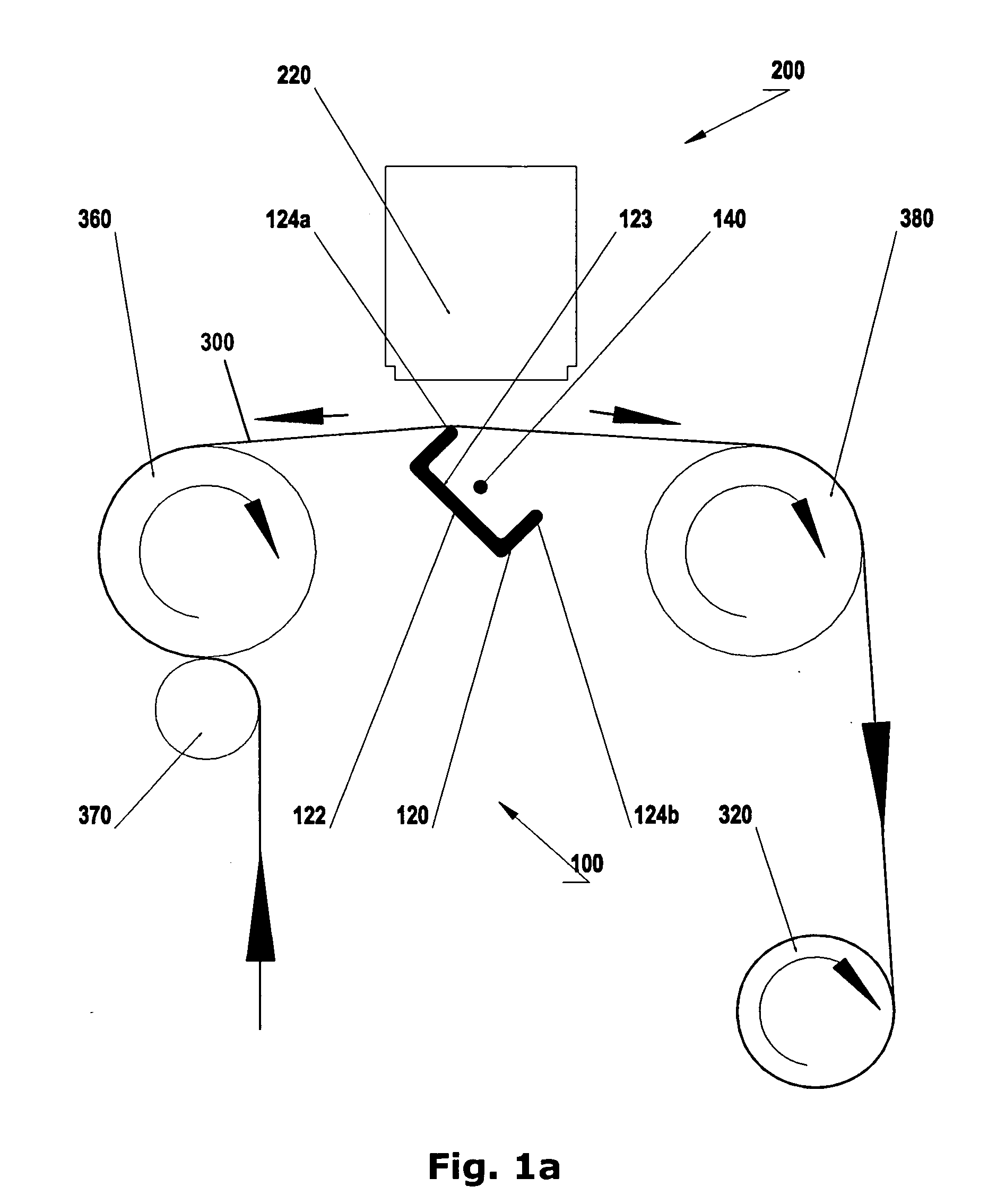
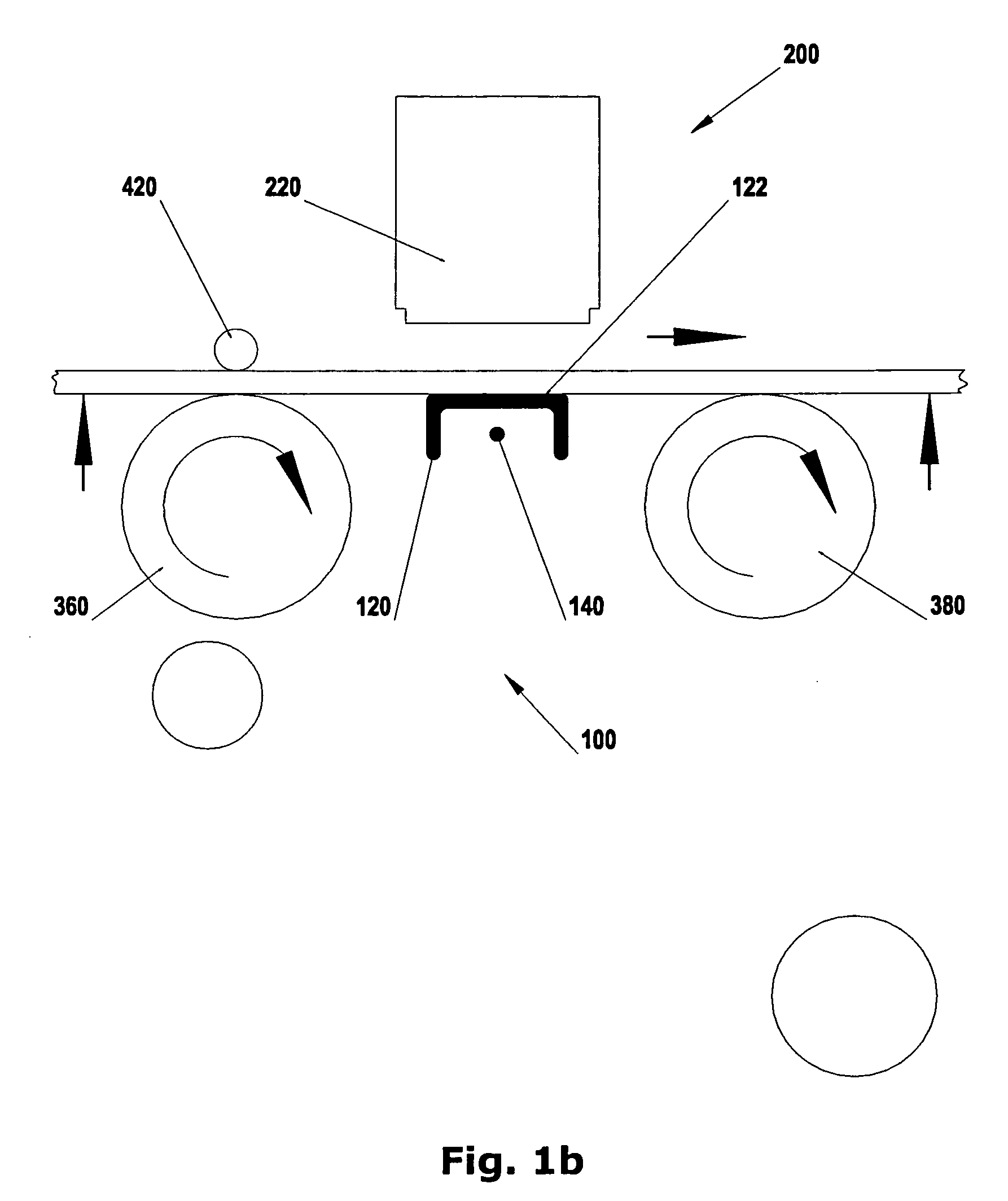
[0044]Reference is now made to FIGS. 1a and 1b showing a reversible printing table 100 according to the invention incorporated into a digital inkjet printer 200 that can print onto material fed by two separate feed modes: either onto a continuous flexible sheet material fed by a roll to roll system, or onto discontinuous sheets such as previously printed on flat-bed printers.

[0045]In order to achieve high resolution printing onto a flexible substrate, such as fabric or paper for example, it may be desirable to stretch the flexible substrate over a knife-edge opposite the print head 220. The section of the substrate being printed upon is kept tensioned thereby, making it stiffer and less prone to distortion. Moreover, flexible material under tension undergoes strain and thus a larger area of material is presented below the print head, thereby enabling printing with a higher resolution onto the taut material, and resulting in a higher resolution when tension is released.

[0046]On the o...

fourth embodiment

[0057]FIG. 4 shows the printing table 4100 according to yet the invention. Here the rotatable printing table 4100 is provided with a triangular cross section and mounted upon an axle 4140 such that it may be rotated to present a side 4122 of the triangle or an acute vertex 4124 of the triangle towards the print head 4220. If the vertex 4124 is sufficiently acute, for example less than 45 degrees, the edge subtended along the triangular beam 4120 at the vertex of its cross-section forms a knife-edge. A flexible substrate may then be stretched between two rollers 4360, 4380 over the knife-edge. Alternatively, with a side 4122 of the triangular cross section 4120 presented towards the print head 4220, a flat printing table 4100 is provided more appropriate for rigid substrates 400.

[0058]It will be appreciated that triangular printing tables 4100 actually provide the possibility of presenting three faces to the print head and three vertices. Some or all the faces may be different, or si...

fifth embodiment

[0060]FIGS. 5a and 5b show a schematic representation of a rotatable printing table 5100 according to the invention. The printing table 5100 has two substrate supports 5122, 5124 mounted upon a rotatable beam 5120 and which may be presented to a print head 5220 selectively to provide two printing modes. The first printing mode, shown in FIG. 5a, is particularly appropriate for printing onto porous media 500, and in particular, for printing onto meshes, where substantial amounts of ink pass through the media. The first printing mode, is also useful for printing onto flags, where both sides of the media are viewed. The second printing mode, shown in FIG. 5b, is generally more appropriate printing onto non-porous substrates 600.

[0061]Referring now specifically to FIG. 5a, the printing table 5100 is shown, configured to print onto porous substrates 500, particularly mesh, but also webbing, netting, woven fabric or the like. The support beam 5120 is configured such that a U-shaped substr...


PUM


Abstract

A printing table for supporting a substrate opposite a print-head. The printing table comprises a plurality of substrate supports which are selectively presentable towards the print head.

Description

PRIORITY INFORMATION[0001]The present invention claims priority to Israel Patent Application No. IL 192713 filed Jul. 9, 2008, making reference hereto in its entirety.FIELD OF THE INVENTION[0002]The present invention is directed to providing a printer, particularly but not exclusively a wide format inkjet printer, that is capable of high quality printing onto both rigid and flexible substrates.BACKGROUND[0003]Wide format inkjet printing is commonly used for printing posters, wall decorations, signs and the like. The medium to be printed, if flexible, is typically provided on a continuous roll and is advanced, roll to roll, past the print head. Sometimes however, particularly when printing onto a stiff material, the material to be printed is provided in sheet form and the printing technique is then known as flat-bed printing. The wider the sheet, the greater the tendency for it to be warped or misaligned whilst being fed past the print head, and a great deal of effort has been expend...

Claims


Application Information

Patent Timeline
IPC IPC(8): B41F21/00
CPCB41J11/14B41J11/02
Inventor SHAPIRA, GUR
Owner MATAN DIGITAL PRINTERS
Why Eureka
Try Eureka