
Coverage Enhancement Using Dynamic Antennas and Virtual Access Points

a dynamic antenna and virtual access point technology, applied in the direction of network topologies, broadcast service distribution, wireless commuication services, etc., can solve the problems of difficult communication within the wireless lan b>100/b>, and achieve the effect of quick roaming decision

Active Publication Date: 2010-01-14
ARRIS ENTERPRISES LLC
View PDF100 Cites 21 Cited by
  • Summary
  • Abstract
  • Description
  • Claims
  • Application Information

AI Technical Summary

Benefits of technology

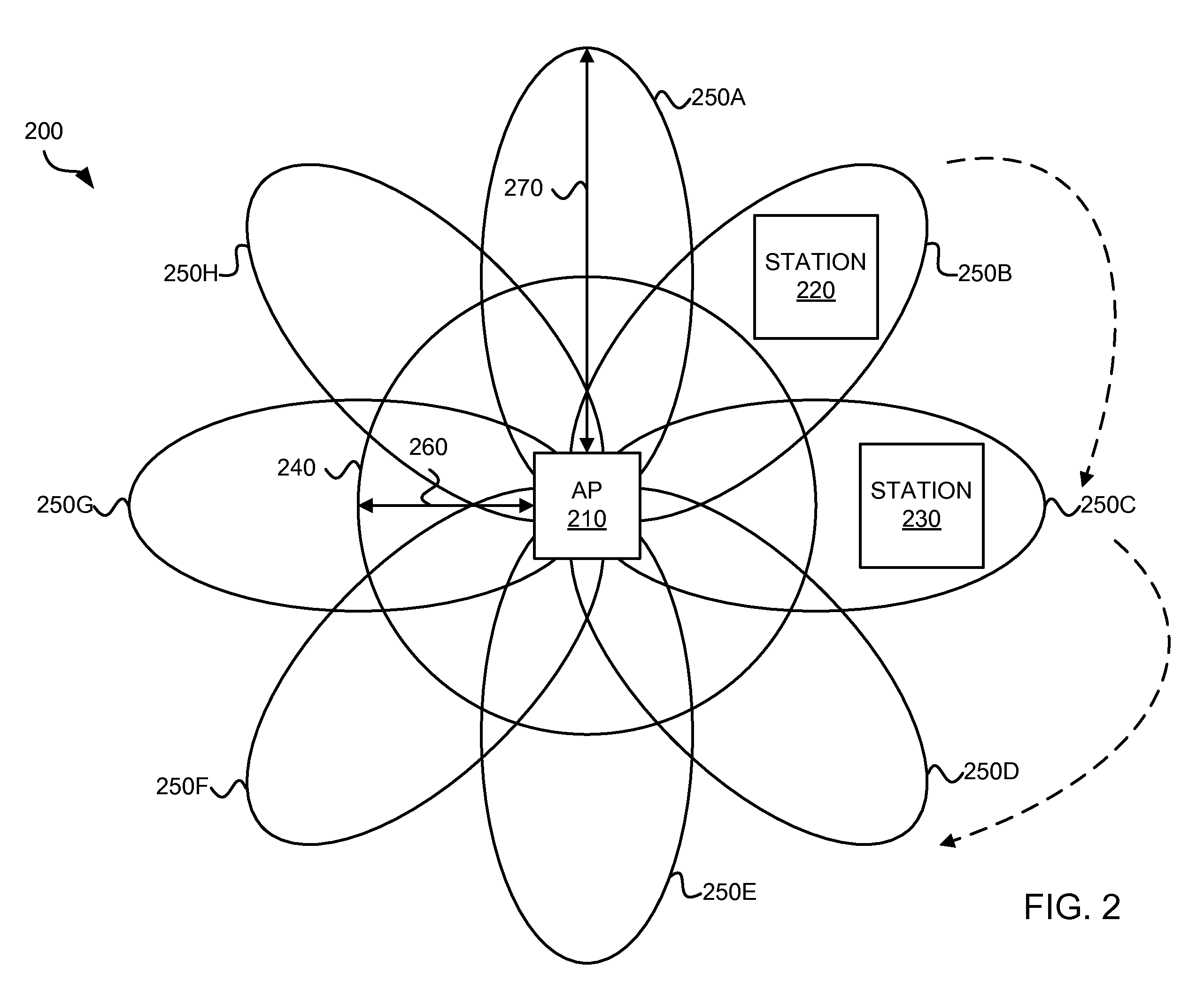
The invention provides access points for enhanced coverage using dynamic antennas. These access points have a processor and an antenna apparatus that can provide multiple directional antenna patterns for communication over a wireless local area network. The processor maps multiple virtual access points to the directional antenna patterns and transmits a broadcast communication on each virtual access point. This allows for enhanced coverage with directed coverage and virtual access points, improving communication with distant stations and ensuring broadcast communication. The technical effect of the invention is improved coverage and synchronization with stations operating in power saving modes.

Problems solved by technology

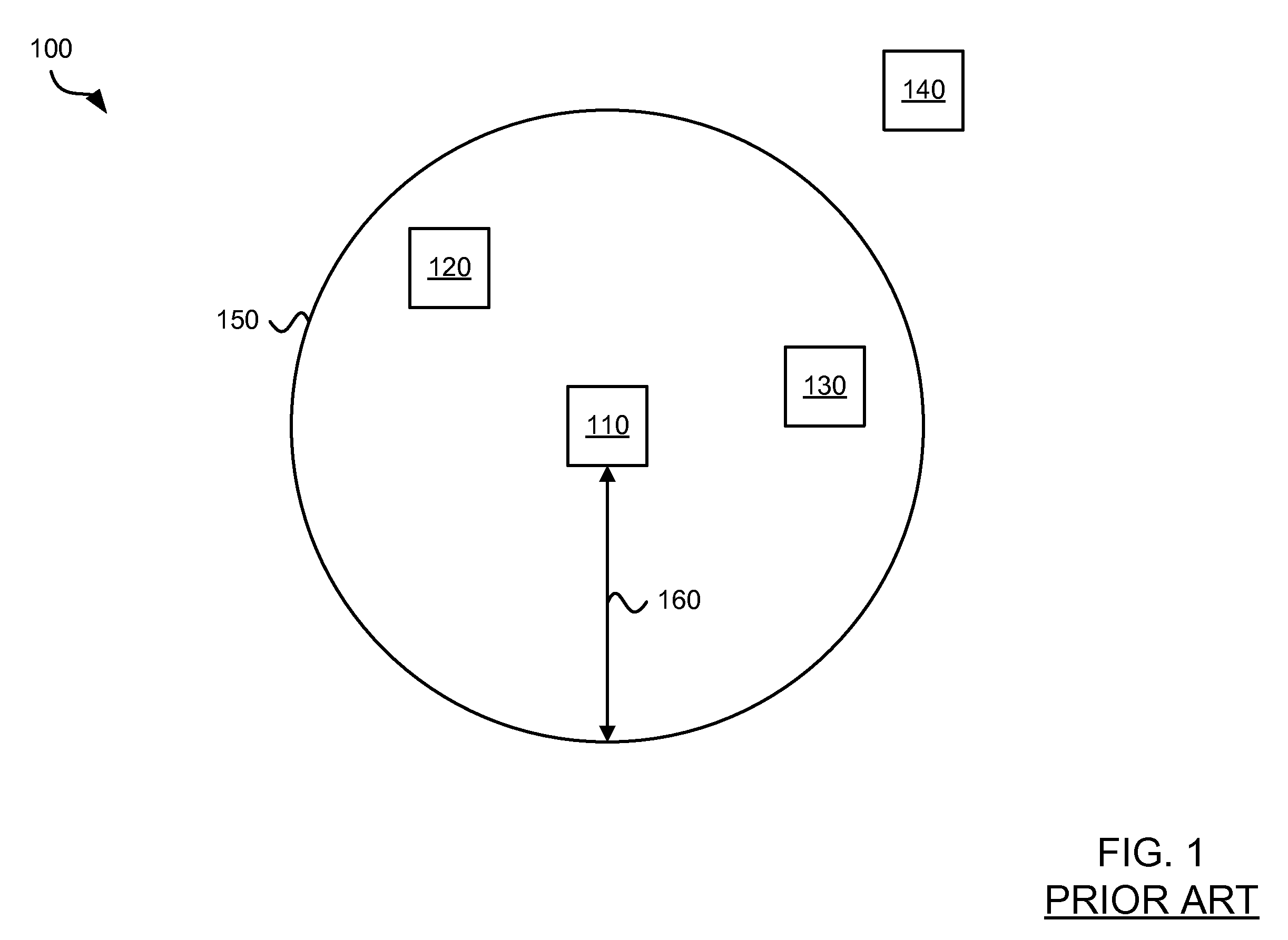
Therefore, without beacons, communication within the wireless LAN 100 becomes difficult.

Method used


Image

  • Coverage Enhancement Using Dynamic Antennas and Virtual Access Points
  • Coverage Enhancement Using Dynamic Antennas and Virtual Access Points
  • Coverage Enhancement Using Dynamic Antennas and Virtual Access Points

Examples


Embodiment Construction

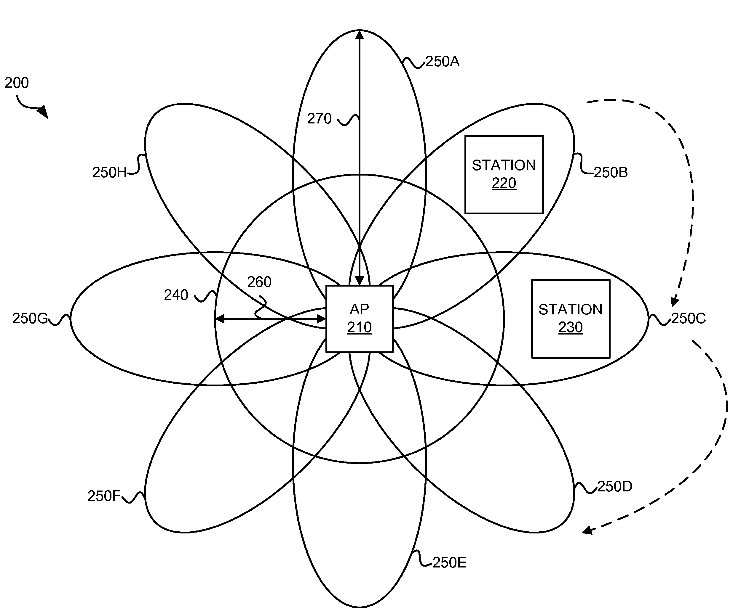
[0023]An access point for enhanced coverage of a wireless local area network includes a processor and an antenna apparatus configured to provide a plurality of directional antenna patterns for communication over the wireless local area network. In some embodiments, the access point transmits beacons on each of the plurality of directional antenna patterns, for example, in a round-robin manner. Each of the directional antenna patterns extends further in length (although more concentrated in width) from the access point than an omnidirectional pattern of the antenna apparatus. Therefore, the access point transmits beacons further from the access point. Additionally, the sum coverage area of each of the directional antenna patterns, averaged over individual transmissions on each of the directional antenna patterns, is greater than the coverage area of the omnidirectional antenna pattern.

[0024]In some embodiments, the access point maps a plurality of virtual access points, each virtual ...


PUM


Abstract

Mechanisms for wireless local area network coverage enhancement using dynamic antennas are provided. The dynamic antennas may be used, for example, in an antenna apparatus of an access point. The access point maps a plurality of virtual access points (VAPs), each VAP corresponding to at least one of a plurality of directional antenna patterns of the antenna apparatus. The processor transmits broadcast communication on each of the VAPs a further distance from the access point as compared to transmitting on an omnidirectional antenna pattern of the antenna apparatus.

Description

CROSS-REFERENCE TO RELATED APPLICATION[0001]The present application is a divisional and claims the priority benefit of U.S. patent application Ser. No. 11 / 413,293 filed Apr. 28, 2006 and entitled “Coverage Enhancement Using Dynamic Antennas,” which in turn claims the priority benefit of U.S. provisional application No. 60 / 702,730 filed Jul. 26, 2005 and entitled “Mechanism for Wireless LAN Coverage Enhancement Using Dynamic Antennas.”[0002]The present application is related to co-pending U.S. patent application Ser. No. 11 / 041,145 filed Jan. 21, 2005 and entitled “System and Method for a Minimized Antenna Apparatus with Selectable Elements,” U.S. patent application Ser. No. 11 / 022,080 filed Dec. 23, 2004 and entitled “Circuit Board having a Peripheral Antenna Apparatus with Selectable Antenna Elements,” U.S. patent application Ser. No. 11 / 010,076 filed Dec. 9, 2004 and entitled “System and Method for an Omnidirectional Planar Antenna Apparatus with Selectable Elements,” U.S. patent ...

Claims


Application Information

Patent Timeline
Patent Type & Authority Applications(United States)
IPC IPC(8): H04W16/26
CPCH04B7/0408H04W88/08H04W84/12H04W4/06H04W16/28
Inventor KISH, WILLIAM
Owner ARRIS ENTERPRISES LLC
Learn More