Ducted fan assembly for radio-controlled model

a technology of ducted fan and radio control, which is applied in the direction of toy aircraft, liquid fuel engines, positive displacement liquid engines, etc., can solve the problems of ineffective heat dissipation, noise and efficiency reduction, and cumbersome ducted fan assembly b>10/b> in the r/c model airplan

Inactive Publication Date: 2010-01-14
EPF HOBBY
View PDF0 Cites 10 Cited by
  • Summary
  • Abstract
  • Description
  • Claims
  • Application Information

AI Technical Summary

Problems solved by technology

The conventional ducted fan assembly 10 has several disadvantages as follows:1. Ineffective heat dissipation.
This makes installation of the conventional ducted fan assembly 10 in the R / C model airplane a cumbersome task.3. Noise and reduced efficiency.
This may result in air leaks if sealing is not conducted properly.
Hence, when the propeller unit 13 induces an airflow through the housing 11, if an airtight seal is not in place, the airflow can escape through the hole to thereby generate unwanted noise and reduce the efficiency of the conventional ducted fan assembly 10.

Method used


Image

  • Ducted fan assembly for radio-controlled model
  • Ducted fan assembly for radio-controlled model
  • Ducted fan assembly for radio-controlled model

Examples


Embodiment Construction

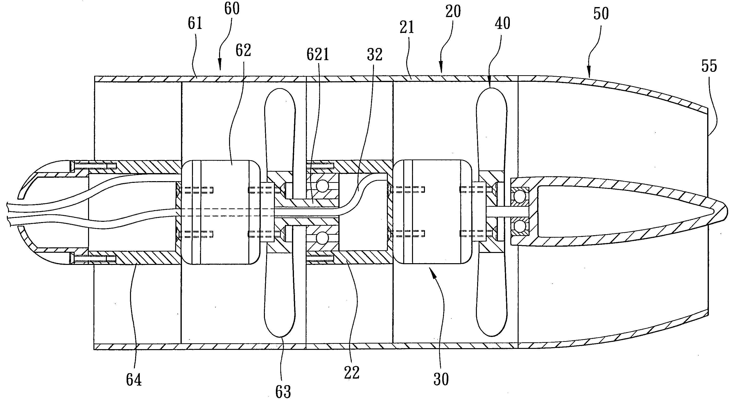
[0019]The preferred embodiments of a ducted fan assembly according to the present invention are illustrated in FIGS. 2 to 7 and can be used on a radio-controlled (R / C) model, e.g., an R / C model airplane, an R / C model motorboat, etc.

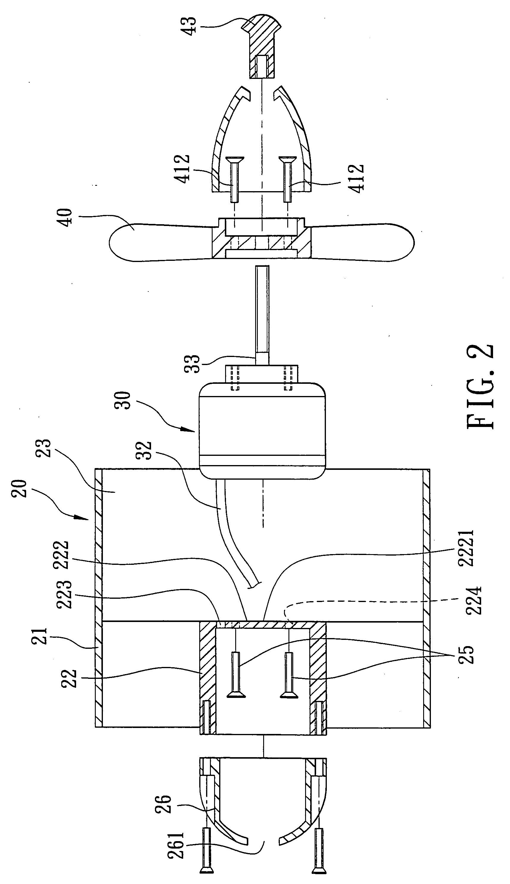
[0020]In the first preferred embodiment shown in FIGS. 2, 3, and 4, the ducted fan assembly includes a housing unit 20, a motor 30, and a propeller 40. In this embodiment, the motor 30 is an external rotor motor. The housing unit 20 defines a chamber 23 and includes a duct member 21, and a hollow seat member 22 disposed in the duct member 21. The motor 30 is mounted to an exterior of the seat member 22 and is disposed in the chamber 23, and includes a power cord 32 extending through the seat member 22. In the first preferred embodiment, the motor 30 further includes a threaded shaft 33 to which a first cap 43 is fastened. However, in view of the fact that the motor 30 is an external rotor motor in the first preferred embodiment as described above, and sin...


PUM


Abstract

A ducted fan assembly includes a housing unit, a motor, and a propeller. The housing unit includes a duct member, and a hollow seat member disposed in the duct member. The motor is mounted to an exterior of the seat member, and includes a power cord extending through the seat member. The propeller is mounted to the motor and is driven thereby to generate an airflow that flows through the duct member and that acts on the motor.

Description

BACKGROUND OF THE INVENTION[0001]1. Field of the Invention[0002]This invention relates to a radio-controlled model, more particularly to a ducted fan assembly for use on a radio-controlled model airplane.[0003]2. Description of the Related Art[0004]As illustrated in FIG. 1, a conventional ducted fan assembly 10 for a hobby radio controlled (R / C) model airplane includes a housing 11, an electric motor 12 disposed inside the housing 11, and a high-speed propeller unit 13 mounted on one end of the electric motor 12. The housing 11 has a seat member 112 that allows mounting of the electric motor 12 thereinside. A power cord 121 passes through the seat member 112 and the housing 11 for connection to a power source (not shown). The motor 12 has a rotating shaft 122 that drives the propeller unit 13.[0005]The conventional ducted fan assembly 10 has several disadvantages as follows:[0006]1. Ineffective heat dissipation. Since the motor 12 is entirely embedded in the seat member 112 and isol...

Claims


Application Information

Patent Timeline
Patent Type & Authority Applications(United States)
IPC IPC(8): F04D19/02F04D13/06
CPCF04D25/06F04D19/007
Inventor YEN, LI-HUA
Owner EPF HOBBY
Why Eureka
Try Eureka