
Huber Needle Assembly and Method of Use

Inactive Publication Date: 2010-01-14
KASHMIRIAN AVTAR SINGH +3
View PDF13 Cites 12 Cited by
  • Summary
  • Abstract
  • Description
  • Claims
  • Application Information

AI Technical Summary

Benefits of technology

[0010]As noted above, when the needle sub-assembly is raised, the needle point is preferably located between the guide members of the base sub-assembly which then serve as guards that prevent finger contact with the needle point. As also noted, it is preferable that some form of locking means is formed between the needle sub-assembly and the base sub-assembly so that, once fully withdrawn upwardly, the needle sub-assembly cannot be again pushed down to re-expose the needle point. This is conveniently achieved by arranging the lock means to operate between the wings and the guide members.
[0044]It will be noted that rebound needle-stick cannot occur in the procedure described because the needle assembly is held firmly on the skin of the patient until the needle is fully withdrawn. Furthermore, since the guide members and the wings can be quite slim and can fit into recesses on the horizontal portion of the base sub-assembly, the needle assembly will lie flat on the skin of the patient and will not be prone to catching on clothing or bed linen. It can also be taped down in a simple and effective manner. In addition, since the wings of the needle sub-assembly can be made as long and as wide as desired, a good gripping surface can be formed for sure and convenient movement of the needle sub-assembly during insertion and withdrawal of the needle.

Problems solved by technology

Unfortunately, this hardly mitigates the danger of rebound needle-stick because such injury is highly likely to occur before the guard can be swung into place.
Withdrawal of the needle without pressing down on the pad results in a fully exposed needle being withdrawn (with the danger of rebound needle-stick) and the need to then manipulate the assembly to effect guarding of the exposed needle (with the additional danger of ‘normal’ needle-stick injury).
A similar danger is evident in the simpler guarded Huber needle assembly of U.S. Pat. No. 5,951,522 to Rosato where the guard is a sort of lazy tongs that can be pushed down over the needle after withdrawal.
If this assembly is used as intended, the housing is pressed down around the puncture site as the needle is being withdrawn, but it is prone to inadvertent misuse by simply pulling on the housing to withdraw the needle, thereby dangerously exposing the user to rebound needle-stick.
Also, being bulky, the housing does not lie flat on the patient's skin and is in danger of catching on clothing or bed linen.

Method used


Image

  • Huber Needle Assembly and Method of Use
  • Huber Needle Assembly and Method of Use
  • Huber Needle Assembly and Method of Use

Examples


Embodiment Construction

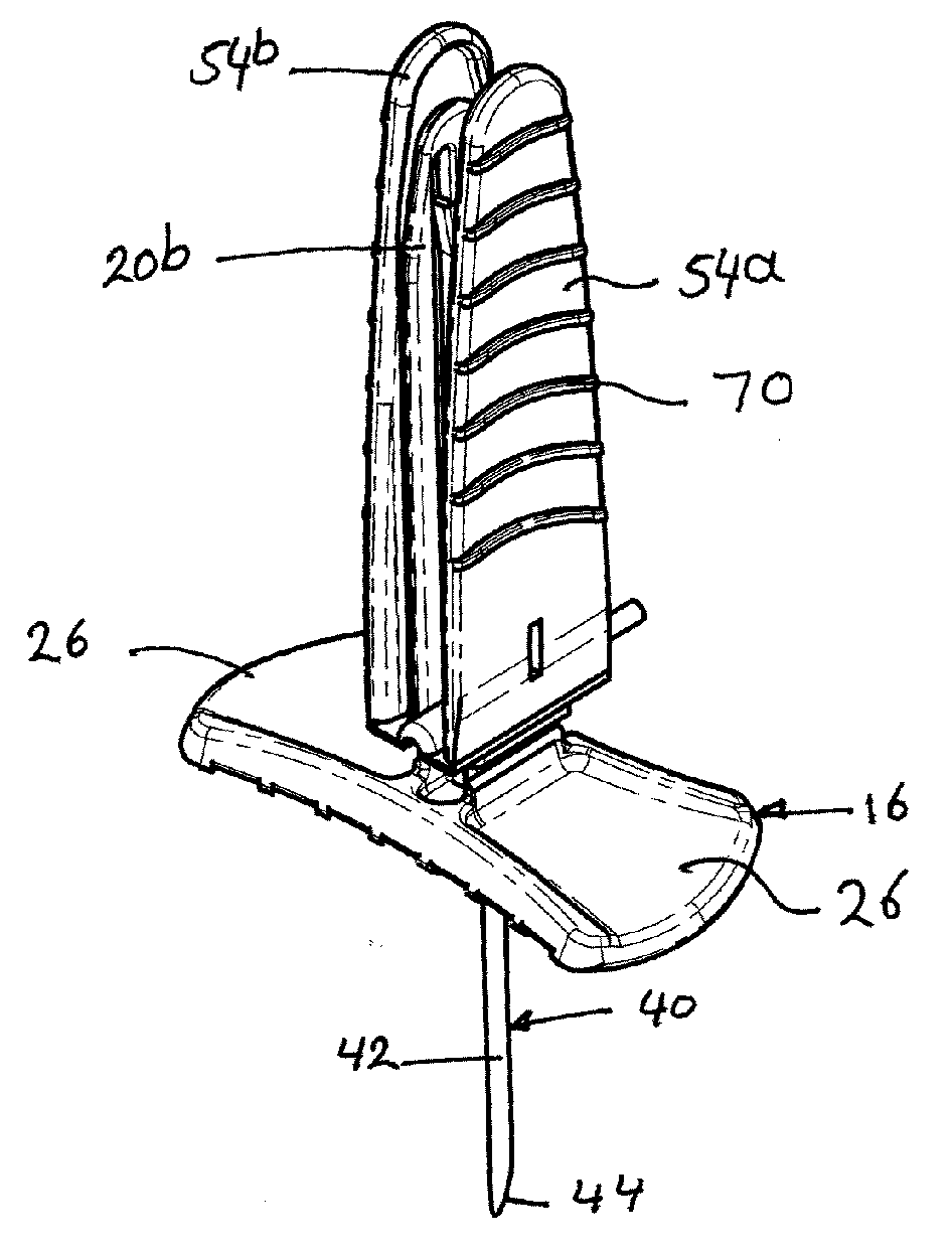
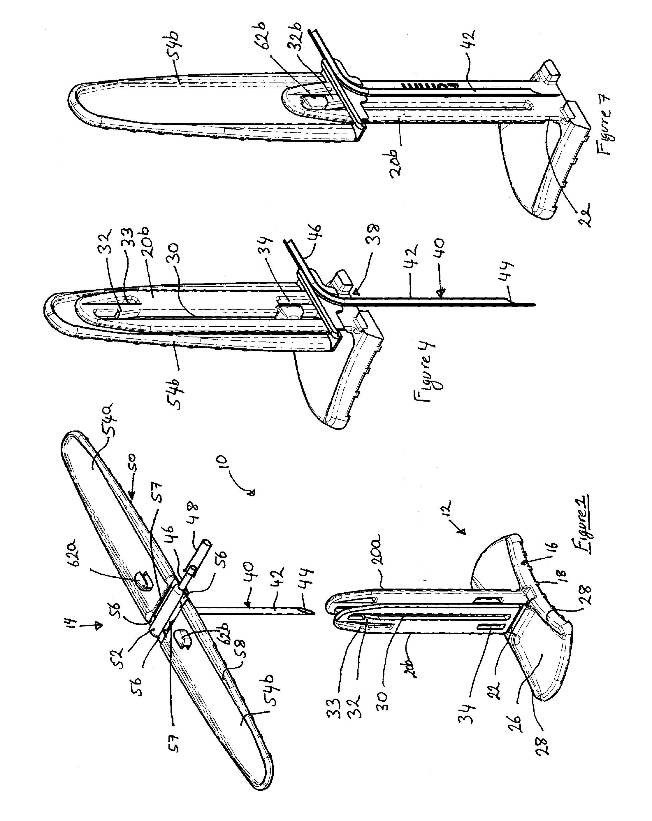
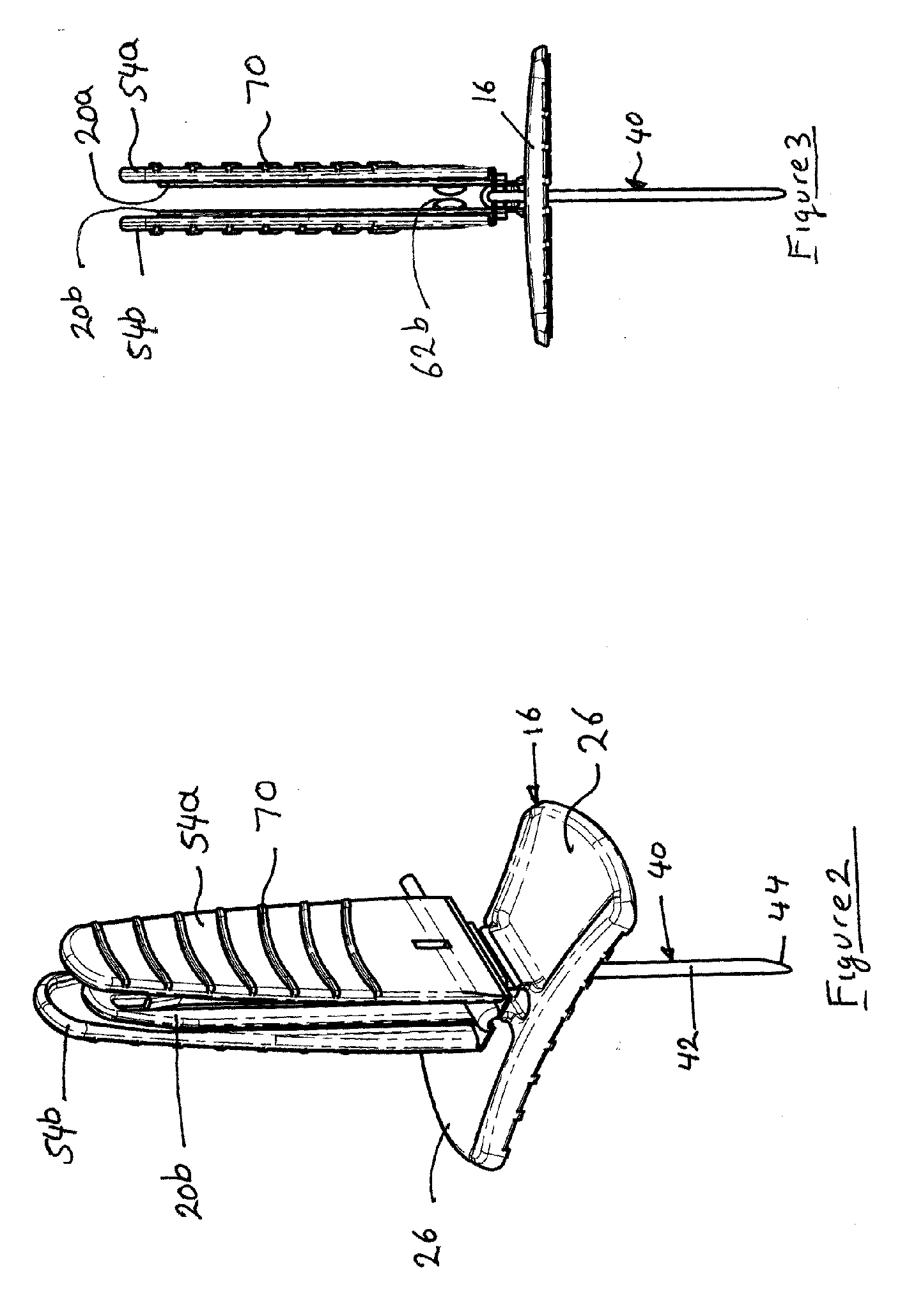
[0062]The Huber needle assembly of a first example, shown in FIGS. 1 to 7, is generally indicated at 10 and its component base and needle sub-assemblies at 12 and 14 respectively.

[0063]The base sub-assembly 12 is conveniently injection-molded in one-piece from a plastic such as PVC or polypropylene so as to have an elongate foot 16 with a ribbed or patterned bottom face 18 and a pair of opposed strip-like guide members 20a and 20b that are each attached by a narrow integral strip-hinge 22 to foot 16 near its center. In use the base sub-assembly 12 is positioned above the injection site and a layer of foam or other padding is sandwiched between the bottom face 18 and the patient's skin. Guide members 20a and 20b can be swung outwards and downwards about their respective hinges 22 to lie on or near the upper surface 26 of foot 16 which is channeled or grooved for the purpose, having raised sides 28. A long slot 30 with closed ends is formed off-center in each guide member 20a and 20b ...


PUM


Abstract

A Huber needle assembly (10) has a base (12) with hinged guide members (20) about a needle aperture (28). A needle assembly (14) has a Huber needle (40) mounted between two hinged wings (54). The guide members (20 ) are movable between a parallel arrangement in which the needle may move vertically between the guide members (20) and a horizontal arrangement in which the needle (40) is locked in the in use position.

Description

TECHNICAL FIELD[0001]This invention relates to Huber needle assemblies of the right angle type in which a fluid delivery or extraction tube is arranged substantially at right angles to the needle point. This is normally achieved by employing a metal needle having a right angle bend. The invention is also concerned with methods of using Huber needle assemblies.BACKGROUND OF THE INVENTION[0002]Huber needle assemblies are commonly used to access subcutaneously implanted medication ports that may be connected to patients' blood vessels or organs for the delivery of a series of liquid medications over an extended period of time for the purpose of chemotherapy, pain management, hormone delivery, microbial control or the like. In some cases, the ports act as reservoirs of therapeutic drugs that are replenished from time to time liquid using a Huber needle. The implanted ports normally have septums of silicone plastic that lie a little below the skin and can be penetrated by a Huber needle ...

Claims


Application Information

Patent Timeline
IPC IPC(8): A61M5/32
CPCA61M5/158A61M2005/1583A61M2005/1581
Inventor KASHMIRIAN, AVTAR SINGHWILSON, CRAIG DOUGLASBASSETTI, DAVID EVANWHELAN, CHRIS
Owner KASHMIRIAN AVTAR SINGH
Features
  • Generate Ideas
  • Intellectual Property
  • Life Sciences
  • Materials
  • Tech Scout
  • Unparalleled Data Quality
  • Higher Quality Content
  • 60% Fewer Hallucinations
Learn More