Heat uniforming device for electronic apparatus

a technology for electronic devices and uniforming devices, which is applied in lighting and heating apparatuses, cooling/ventilation/heating modifications, semiconductor devices, etc., can solve problems such as heat emission, heat may become more serious, and heat dissipation of electronic elements such as cpus, and achieve enhanced capillary attraction and ensure wide space for vapor

Inactive Publication Date: 2010-01-21
ELECTRONICS & TELECOMM RES INST
View PDF14 Cites 8 Cited by
  • Summary
  • Abstract
  • Description
  • Claims
  • Application Information

AI Technical Summary

Benefits of technology

[0017]In a heat uniforming device for an electronic apparatus according to the present invention, a multi-channel capillary structure is formed in each of plates that constitute an evaporation unit and a condensation unit so that the circulation of operating fluid can be improved by evaporation and condensation of the operating fluid due to enhanced capillary attraction. Also, the backward...

Problems solved by technology

Due to an improvement in the performance of personal computers (PCs) and an increase in the integration density of packages, the dissipation of heat generated by electronic elements, such as a central processing unit (CPU), has become an important issue.
As leading-edge processing technology used for CPUs for PCs has also been applied to other electronic apparatuses, the emission of heat has become problematic in a wide range of electronic apparatuses.
For example, as portable phones that need to be designed at a higher density than notebook computers become more highly efficient at the current development speed, the problem of heat may become more serious.
However, it is difficult to efficiently dissipate heat by attaching to the electronic apparatus a heat sink for d...

Method used


Image

  • Heat uniforming device for electronic apparatus
  • Heat uniforming device for electronic apparatus
  • Heat uniforming device for electronic apparatus

Examples


Embodiment Construction

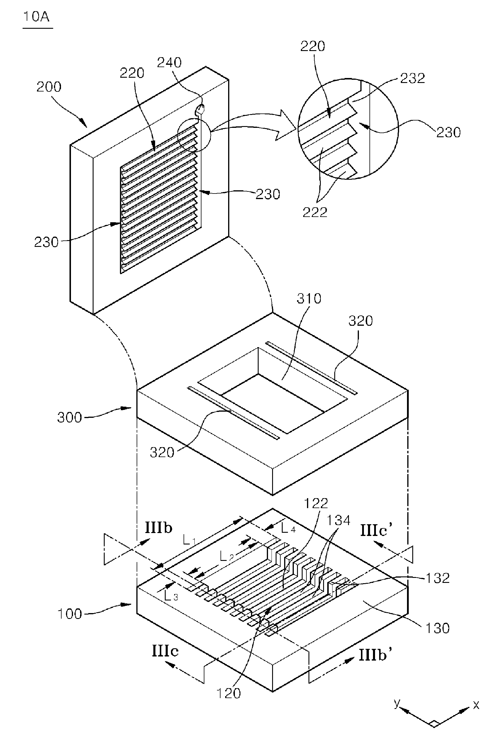
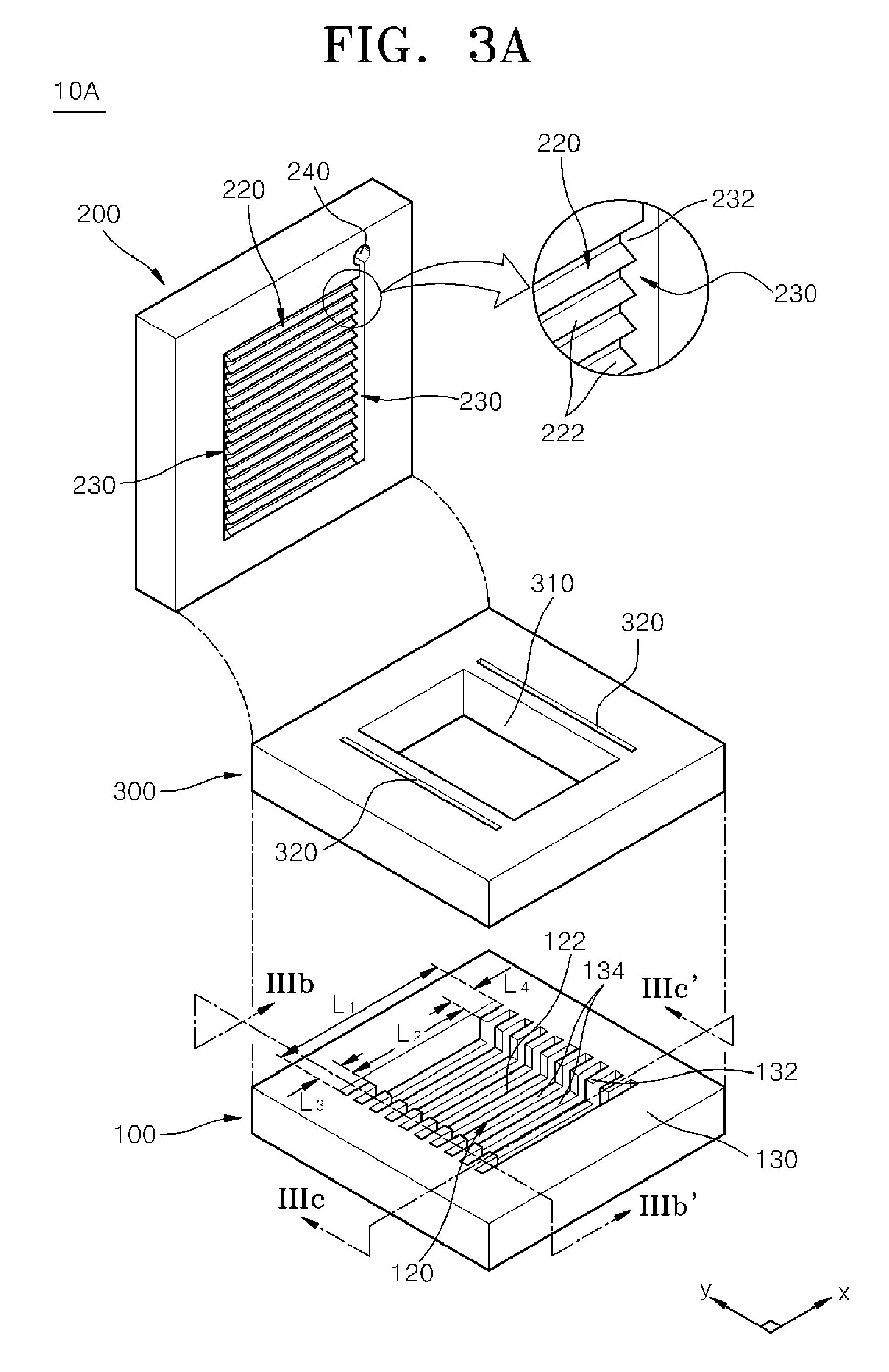
[0035]FIG. 3A is an exploded perspective view of an essential part of a heat uniforming device 10A for an electronic apparatus according to an embodiment of the present invention.

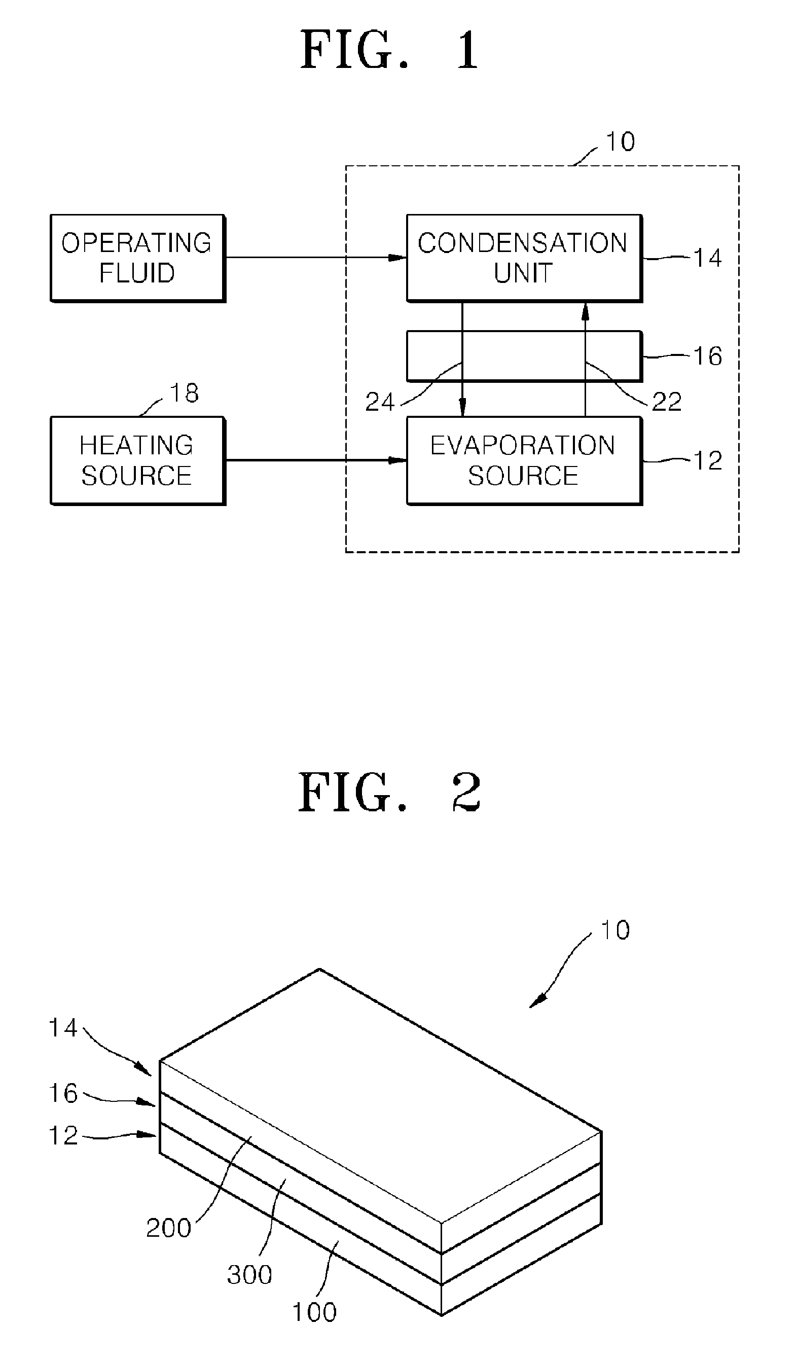
[0036]Referring to FIG. 3A, the heat uniforming device 10A for the electronic apparatus according to the embodiment of the present invention includes a first plate 100, which constitutes the evaporation unit 12, a second plate 200, which constitutes the condensation unit 14, and a third plate 300, which constitutes the connection unit 16 and is interposed between the first and second plates 100 and 200.

[0037]The first plate 100 includes a first multi-channel capillary region 120 having a plurality of channels 122, which functions to evaporate an externally injected operating fluid due to heat transmitted from a heating source 18.

[0038]The second plate 200 constituting the condensation unit 14 includes a second multi-channel capillary region 220 and a return region 230. The second multi-channel capillary reg...


PUM


Abstract

Provided is a heat uniforming device for an electronic apparatus, which improves the flow and circulation of operating fluid through evaporation and condensation using capillary attraction. The heat uniforming device for the electronic apparatus includes: an evaporation unit comprised of a planar first plate including a first multi-channel capillary region for evaporating an externally injected operating fluid due to heat transmitted from a heating source; and a condensation unit comprised of a planar second plate including a second multi-channel capillary region for condensing vapor supplied from the evaporation unit and a return region having a fluid path that communicates with all channels of the second multi-channel capillary region.

Description

TECHNICAL FIELD[0001]The present invention relates to a heat uniforming device, and more particularly, to a heat uniforming device for an electronic apparatus, which can reduce the flow resistance of heat generated in a specific position of the electronic apparatus.BACKGROUND ART[0002]Due to an improvement in the performance of personal computers (PCs) and an increase in the integration density of packages, the dissipation of heat generated by electronic elements, such as a central processing unit (CPU), has become an important issue. As leading-edge processing technology used for CPUs for PCs has also been applied to other electronic apparatuses, the emission of heat has become problematic in a wide range of electronic apparatuses. For example, as portable phones that need to be designed at a higher density than notebook computers become more highly efficient at the current development speed, the problem of heat may become more serious.[0003]The latest developments involving portab...

Claims


Application Information

Patent Timeline
IPC IPC(8): F28D15/04H05K7/20
CPCH01L23/427H01L2924/0002H01L2924/00F28D15/0233F28D15/0266F28D15/046H05K7/20
Inventor MOON, SEOK-HWANHWANG, GUNN
Owner ELECTRONICS & TELECOMM RES INST
Why Eureka
Try Eureka