
Scan driver and plasma display device using the same

a technology of plasma display device and scanner, which is applied in the direction of optical/shielding arrangement, instruments, computing, etc., can solve the problems of increased problems, malfunction of plasma display device, and inability to detect the scan ic without interruption, so as to improve the operation stability, the effect of sufficient reference potential and raising the emi shielding performan

Inactive Publication Date: 2010-01-21
SAMSUNG SDI CO LTD
View PDF2 Cites 1 Cited by
  • Summary
  • Abstract
  • Description
  • Claims
  • Application Information

AI Technical Summary

Benefits of technology

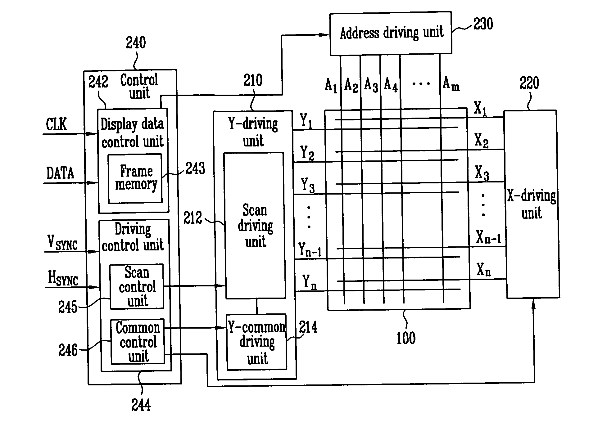
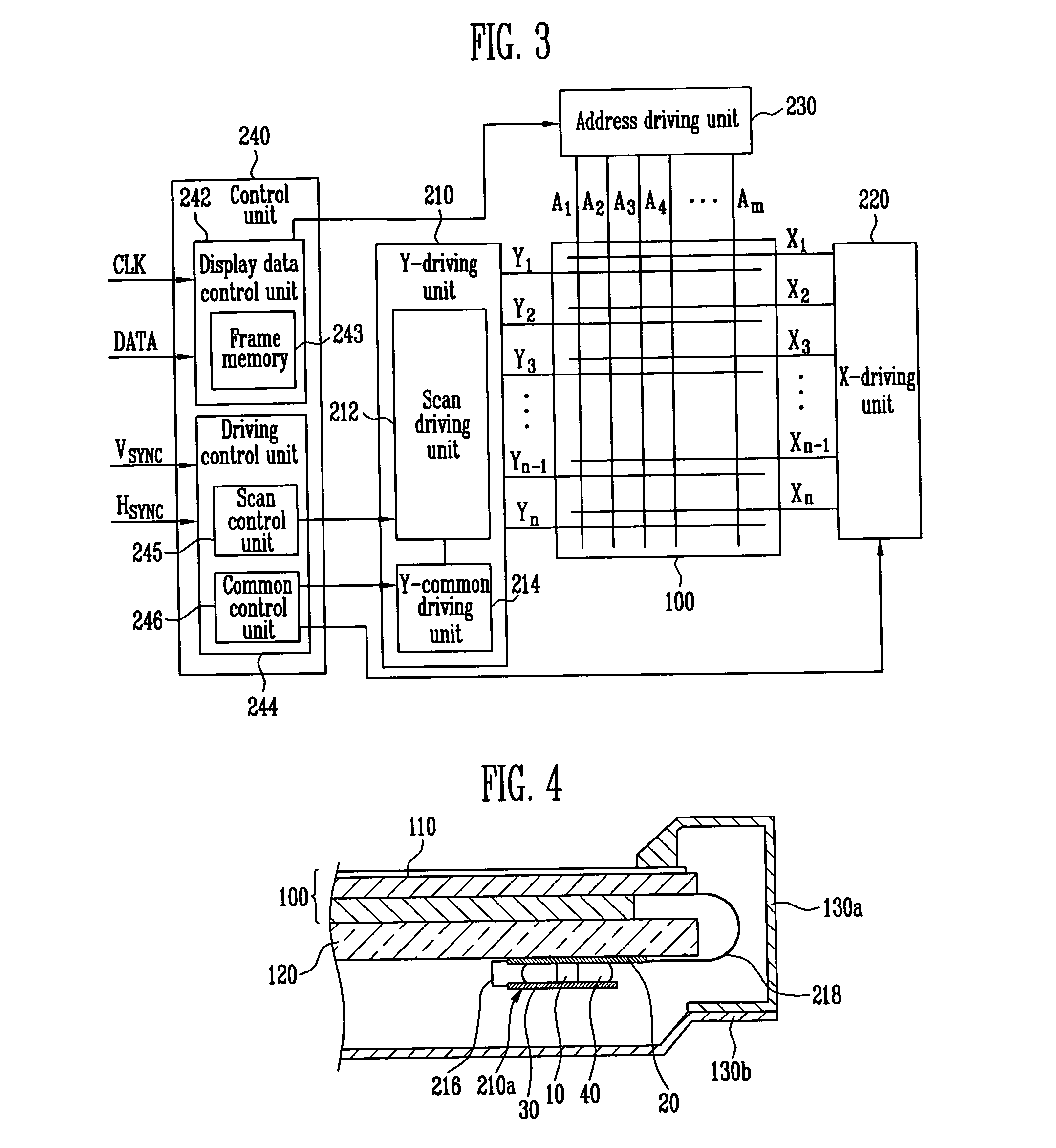
[0008]It is therefore a feature of an embodiment to provide a scan driver capable of securing sufficient reference potential and being coupled to a radiating heat system with ease.
[0009]It is therefore another feature of an embodiment to provide a plasma display device capable of raising EMI shielding performance and improving operation stability by using the scan driver.

Problems solved by technology

However, when a scan driving integrated circuit (scan IC) in a plasma display device uses a floating reference potential, an abrupt voltage change may occur in the scan IC during a sustain period at the time of driving the panel unit.
Abrupt and sudden signal changes, e.g., voltage fluctuations, during a floating state of the scan IC may cause malfunction of the plasma display device, e.g., a defective screen, due to noise generated by the scan IC.
Such problems may be increased when the plasma display device uses a single scan IC.
However, since the conventional driving system including the separate buffer board for the scan IC may require 4-layer printed circuit board (PCB) for manufacturing thereof and the valid area of use in the panel display unit may be small, manufacturing costs of the conventional buffer board for the scan IC may be high.

Method used


Image

  • Scan driver and plasma display device using the same
  • Scan driver and plasma display device using the same
  • Scan driver and plasma display device using the same

Examples


Embodiment Construction

[0024]Korean Patent Application No. 10-2008-0068540, filed on Jul. 15, 2008, in the Korean Intellectual Property Office, and entitled “Scan Driver and Plasma Display Device Using the Same,” is incorporated by reference herein in its entirety.

[0025]Example embodiments will now be described more fully hereinafter with reference to the accompanying drawings; however, they may be embodied in different forms and should not be construed as limited to the embodiments set forth herein. Rather, these embodiments are provided so that this disclosure will be thorough and complete, and will fully convey the scope of the invention to those skilled in the art.

[0026]In the drawing figures, the dimensions of layers and regions may be exaggerated for clarity of illustration. It will also be understood that when a layer or element is referred to as being “on” another layer or substrate, it can be directly on the other layer or substrate, or intervening layers may also be present. Further, it will be ...


PUM


Abstract

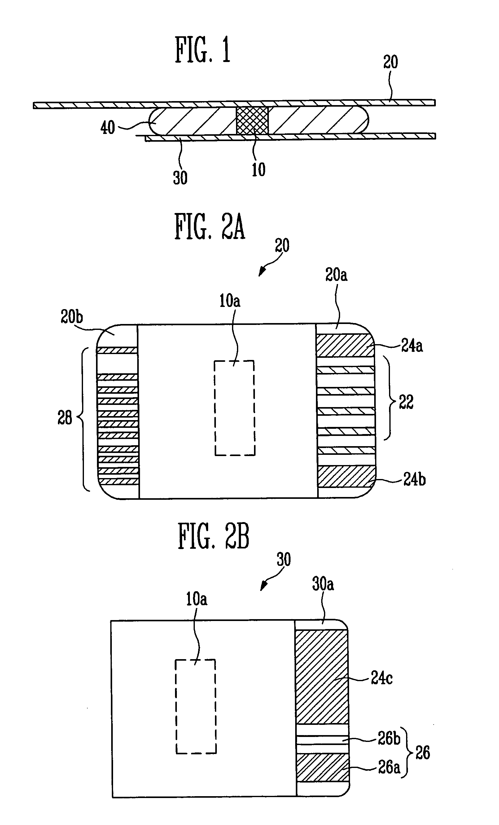
A scan driver includes a scan driving integrated circuit, a first film on a first surface of the scan driving integrated circuit, the first film including at least one first wire adapted to provide reference potential to the scan driving integrated circuit, and a second film on a second surface of the scan driving integrated circuit, the second surface of the scan driving integrated circuit being opposite the first surface, and the second film including at least one second wire adapted to transfer input and output signals.

Description

BACKGROUND[0001]1. Field[0002]Example embodiments relate to a scan driver used for driving a plasma display panel, and to a plasma display device using the same.[0003]2. Description of the Related Art[0004]A plasma display device is a display device displaying an image by generating plasma in a discharge space between two substrates opposed to each other. The generated plasma in the discharge space causes phosphor between the two substrates to emit light.[0005]However, when a scan driving integrated circuit (scan IC) in a plasma display device uses a floating reference potential, an abrupt voltage change may occur in the scan IC during a sustain period at the time of driving the panel unit. Abrupt and sudden signal changes, e.g., voltage fluctuations, during a floating state of the scan IC may cause malfunction of the plasma display device, e.g., a defective screen, due to noise generated by the scan IC. Such problems may be increased when the plasma display device uses a single sca...

Claims


Application Information

Patent Timeline
Patent Type & Authority Applications(United States)
IPC IPC(8): G09G5/00G09G3/28
CPCG09G3/296G09G2300/0426G09G2300/0408H01J11/44
Inventor SONG, YOO-JIN
Owner SAMSUNG SDI CO LTD
Learn More