
Thermal device for heat generating source

Inactive Publication Date: 2010-01-21
HONG FU JIN PRECISION IND (SHENZHEN) CO LTD +1
View PDF55 Cites 5 Cited by
  • Summary
  • Abstract
  • Description
  • Claims
  • Application Information

AI Technical Summary

Benefits of technology

[0004]Developments in the computers are continuing at a rapid pace. Electronic devices in computers, such as central processing units (CPUs), generate a lot of heat during normal operation, which can deteriorate their operational stability, and damage associated electronic devices. Thus, the heat must be removed quickly to ensure normal operation of the CPU. A typical thermal device includes a typical heat sink mounted on a CPU to remove heat. The typical heat sink includes a plurality of parallel fins and several heat pipes passing through the parallel fins. However, the typical thermal device is usually heavy and the efficiency low.

Problems solved by technology

Electronic devices in computers, such as central processing units (CPUs), generate a lot of heat during normal operation, which can deteriorate their operational stability, and damage associated electronic devices.
However, the typical thermal device is usually heavy and the efficiency low.

Method used


Image

  • Thermal device for heat generating source
  • Thermal device for heat generating source
  • Thermal device for heat generating source

Examples


Embodiment Construction

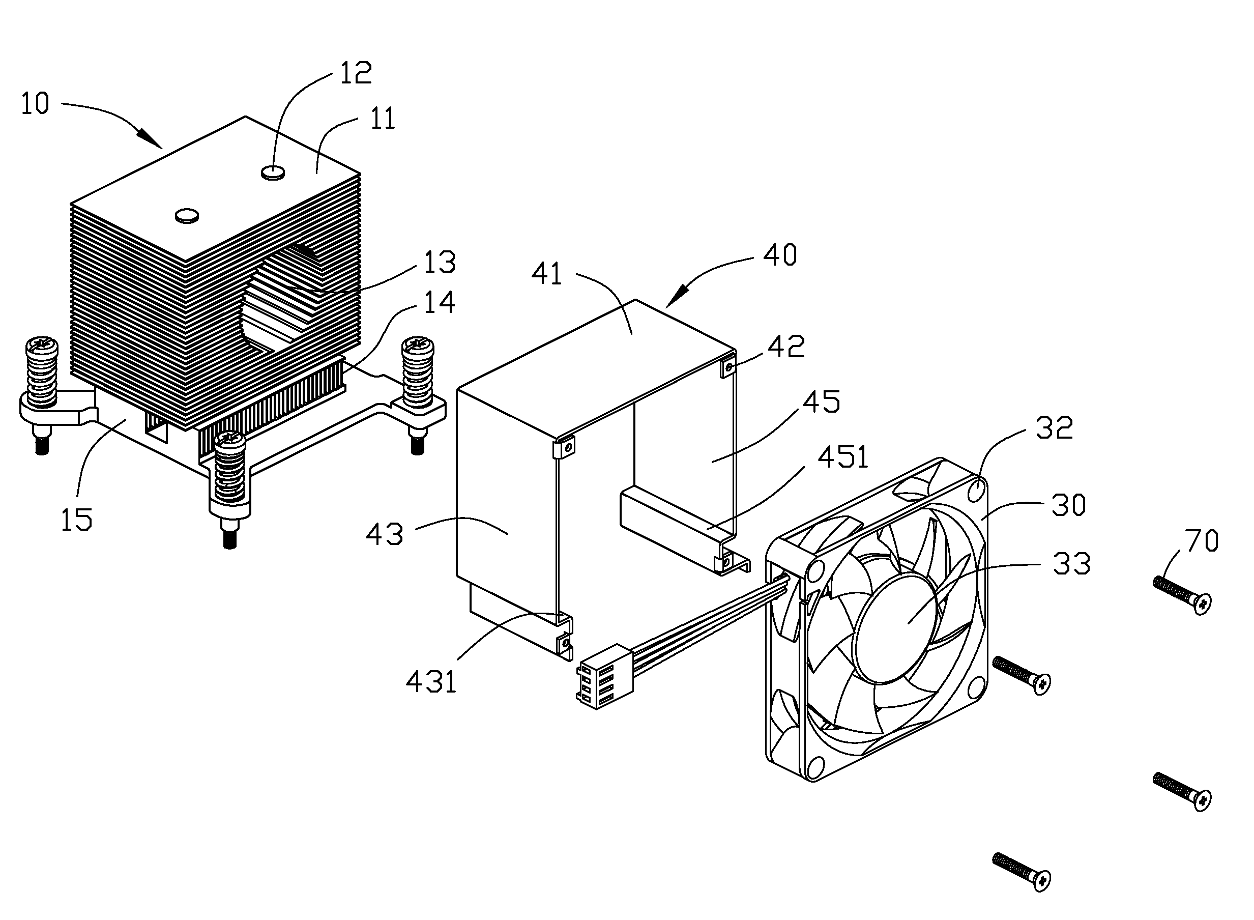
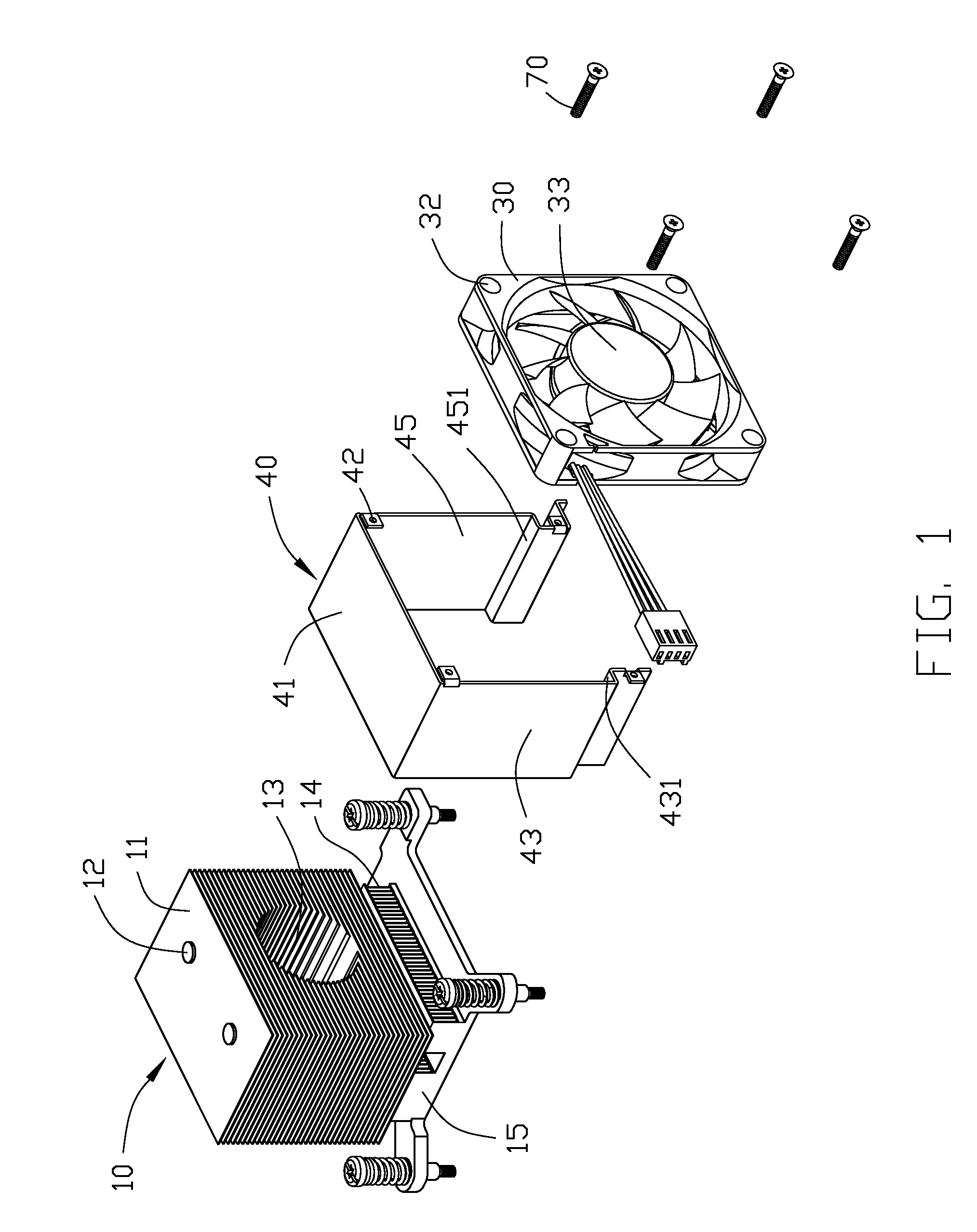
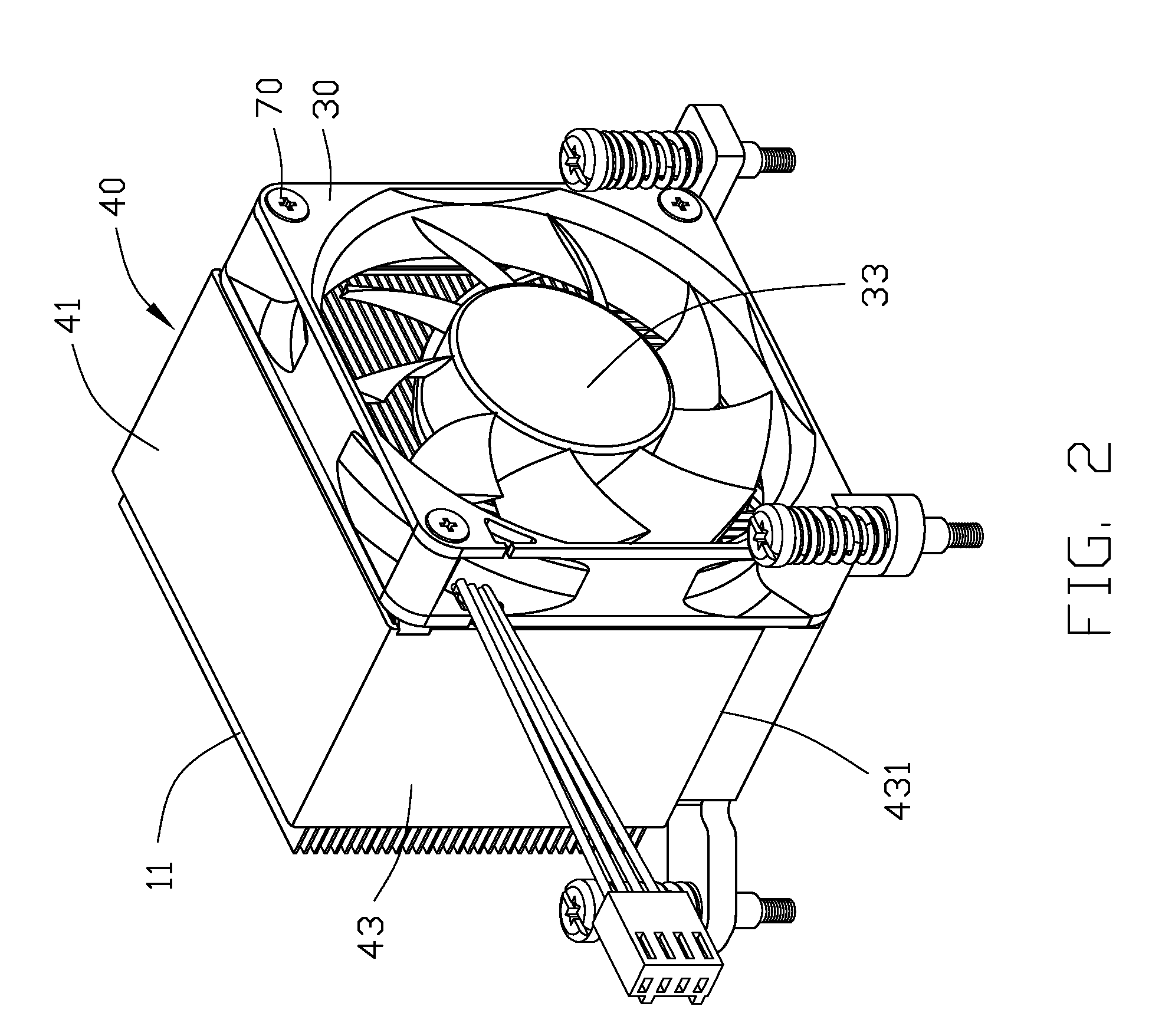
[0008]FIG. 1 is an exploded view of an embodiment of a thermal device for dissipating heat from a heat source. The thermal device includes a heat sink 10, a fan 30, and a mounting bracket 40 for fixing the fan 30 onto the heat sink 10.

[0009]The heat sink 10 includes a base 15, and a U-shaped heat pipe 12 positioned on a top surface of the base 15. A plurality of parallel fins 11 is positioned on and passing through the heat pipe 12. A cutout 13 is defined within the plurality of parallel fins 11 in a shape similar to the shape of a motor 33 on the fan 30. A bottom surface of the base 15 is configured to connect to a heat source, such as a central processing unit (CPU). The heat generated by the heat source is transmitted from the base 15 to the fins 11 via the heat pipe 12. A plurality of perpendicular conducting fins 14 is positioned on the base 15 to transmit the heat from the bottom surface to the top surface of the base 15.

[0010]The mounting bracket 40 is an approximately U-shap...


PUM


Abstract

A heat sink for dissipating heat from a heat source, includes a base configured to connect with a heat source, and a plurality of fins positioned on the base. A cutout is defined within the plurality of parallel fins.

Description

BACKGROUND[0001]1. Technical Field[0002]The present invention relates to a thermal device for dissipating heat from a heat source.[0003]2. Description of Related Art[0004]Developments in the computers are continuing at a rapid pace. Electronic devices in computers, such as central processing units (CPUs), generate a lot of heat during normal operation, which can deteriorate their operational stability, and damage associated electronic devices. Thus, the heat must be removed quickly to ensure normal operation of the CPU. A typical thermal device includes a typical heat sink mounted on a CPU to remove heat. The typical heat sink includes a plurality of parallel fins and several heat pipes passing through the parallel fins. However, the typical thermal device is usually heavy and the efficiency low.[0005]Therefore, a new thermal device for dissipating heat is desired to overcome the above-described deficiencies.BRIEF DESCRIPTION OF THE DRAWINGS[0006]FIG. 1 is an exploded view of an emb...

Claims


Application Information

Patent Timeline
IPC IPC(8): H05K7/20
CPCH01L23/3672H01L2924/0002H01L2924/00
Inventor CAO, LIANG-LIANGLIN, YU-HSUWU, JENG-DACHAO, CHIH-HANGLI, YANGGUO, LEI
Owner HONG FU JIN PRECISION IND (SHENZHEN) CO LTD
Learn More