
Nickel-metal hydride rechargeable cell

Inactive Publication Date: 2009-06-18
FDK CORP
View PDF5 Cites 3 Cited by
  • Summary
  • Abstract
  • Description
  • Claims
  • Application Information

AI Technical Summary

Benefits of technology

[0009]The primary object of the present invention is to provide a nickel-metal hydride rechargeable cell which is reduced in self-discharge for a long period of time, and also reduced in drop of operating voltage.
[0015]The nickel-metal hydride batteries according to the present invention have self-discharge reduced for a long period of time, and therefore do not need recharging in order to be usable, even some period of time after charged.
[0016]Further, the drops in operating voltages of the above-described batteries are suppressed for a long period of time. Thus, when these batteries are used as a power source for an electric or electronic device, the operating voltages of the batteries once charged does not drop to lower than the discharge cut voltage for the electric or electronic device, even some period of time after charging, so that the batteries do not need recharging before use.
[0017]Thus, the above-described batteries are convenient for the user, and at the same time environmentally-friendly, since the reduced self-discharge leads to a reduction in wasteful power consumption.

Problems solved by technology

The nickel-metal hydride rechargeable cell, however, tends to decrease in remaining capacity due to self-discharge, and occasionally, they have to be freshly recharged when used some time after being charged.
The nickel-metal hydride rechargeable cell using such separator as disclosed in the above-mentioned publication does, however, not achieve a sufficient reduction in self-discharge.
When a battery that has dropped in operating voltage is used as a power source for an electric or electronic device, if the operating voltage of the cell is lower than discharge cut voltage (discharge termination voltage), which is set for each device, the device does not work normally.
Further, even if the device works, if the device is designed to detect the remaining capacity of the cell on the basis of the operating voltage thereof and indicate a decrease in remaining capacity on a liquid crystal panel or by means of LEDs, it may be indicated as if the remaining capacity had decreased to an insufficient level, although it is actually sufficient.

Method used

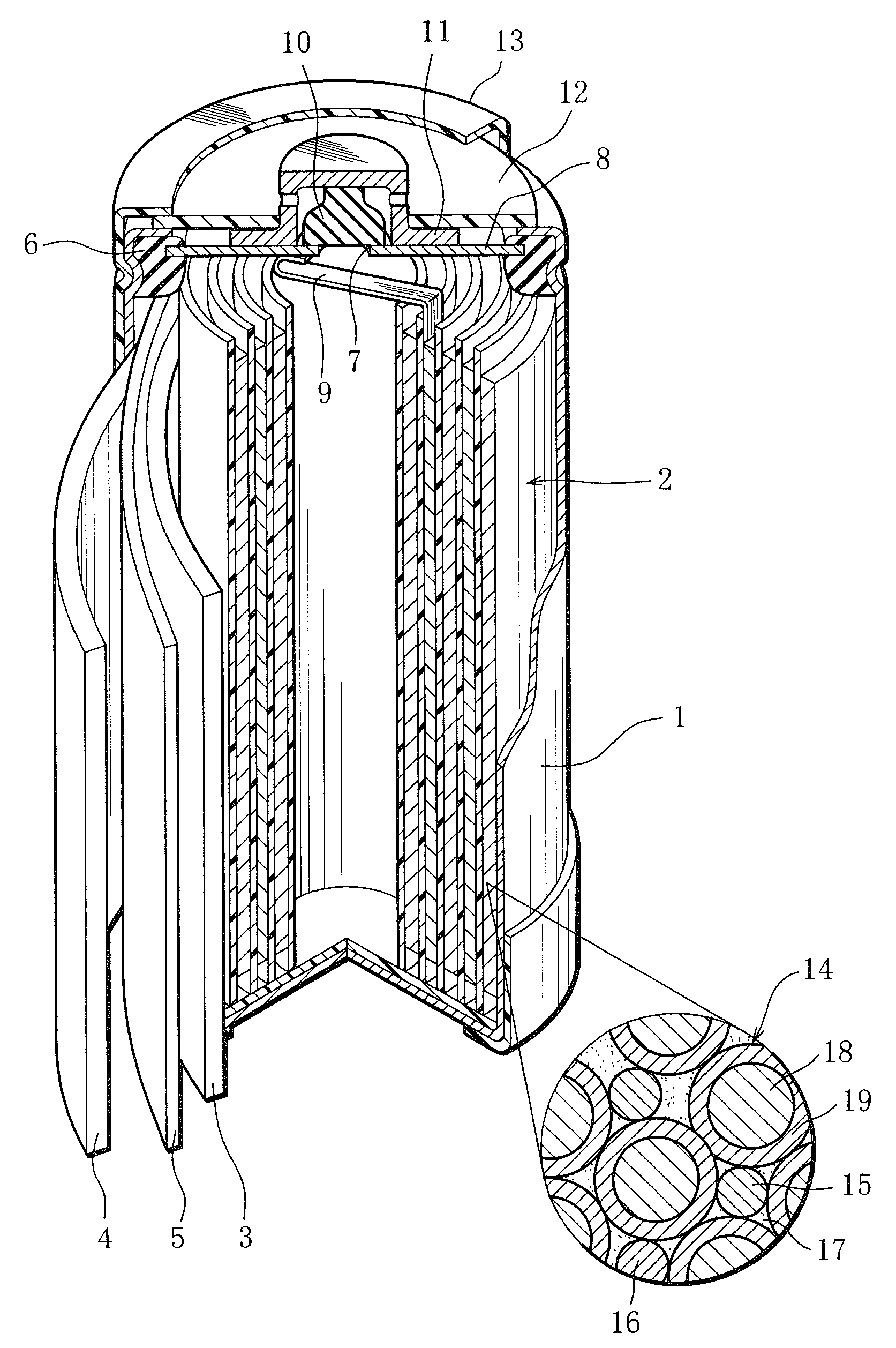

Image

  • Nickel-metal hydride rechargeable cell
  • Nickel-metal hydride rechargeable cell
  • Nickel-metal hydride rechargeable cell

Examples


example 1

1. Preparation of Negative Electrode Plate

[0058]Metal materials were measured out to produce the composition La0.10Ce0.05Pr0.35Nd0.50 Mg0.10Ni3.70Al0.22 and mixed. The mixture was melted in a high-frequency melting furnace and formed into an ingot. The ingot was heated in an argon atmosphere of temperature 1000° C. for 10 hours, thereby causing the crystal structure in the ingot to change into a Ce2Ni7-type or similar structure. Then, the ingot was subjected to mechanical pulverization in an inert atmosphere and then sieving, so that rare earth-Mg—Ni-based hydrogen storage alloy particles of the above composition were obtained. The rare earth-Mg—Ni-based hydrogen storage alloy particles obtained had an average particle size 50 μm. Here, the average particle diameter was defined as a particle size corresponding to 50 percent in weight integration in the particle size distribution of the rare-earth-Mg—Ni-based hydrogen storage alloy particles that was measured with a laser diffraction...


PUM

PropertyMeasurementUnit
Percent by massaaaaaaaaaa
Thicknessaaaaaaaaaa
Lengthaaaaaaaaaa

Abstract

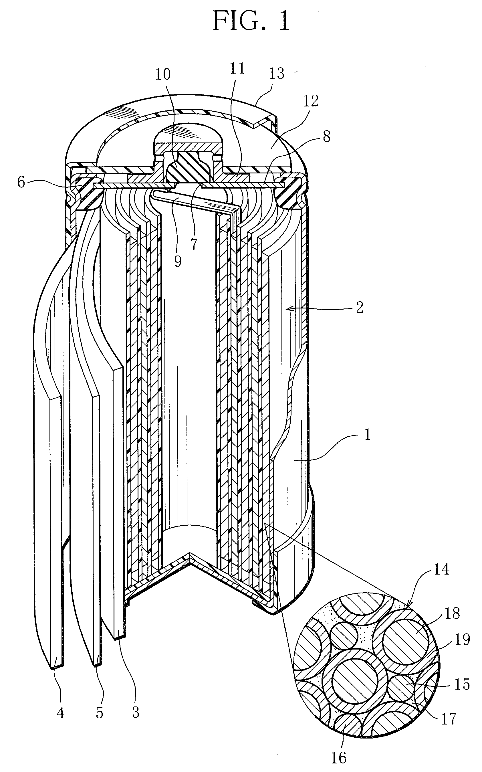
A positive electrode plate (3) of a nickel-metal hydride rechargeable cell contains nickel hydroxide particles (18), a coating layer (19) covering at least a part of a surface of each nickel hydroxide particle (18) and mainly composed of a cobalt compound having an average valence of cobalt more than 2, and Nb-based particles (15) and Y-based particles (16) distributed among the nickel hydroxide particles (18). A negative electrode plate (4) contains a hydrogen storage alloy having a Co content of equal to or less than 2.0% by mass, a separator (5) contains fiber having a sulfo group, and an alkaline electrolyte solution contains sodium hydroxide as a main solute.

Description

TECHNICAL FIELD[0001]This invention relates to a nickel-metal hydride rechargeable cell.BACKGROUND ART[0002]The nickel-metal hydride rechargeable cell can have a high capacity and therefore has a wide range of applications. The nickel-metal hydride rechargeable cell, however, tends to decrease in remaining capacity due to self-discharge, and occasionally, they have to be freshly recharged when used some time after being charged.[0003]In order to alleviate such problems connected with self-discharge, for example the nickel-metal hydride rechargeable cell disclosed in Japanese Unexamined Patent Publication No. Sho 62-115657 uses a separator made of non-woven fabric of sulfonated polyolefin-based resin.[0004]The nickel-metal hydride rechargeable cell using such separator as disclosed in the above-mentioned publication does, however, not achieve a sufficient reduction in self-discharge.[0005]Thus, the inventors of this application have developed a new nickel-metal hydride rechargeable c...

Claims


Application Information

Patent Timeline
IPC IPC(8): H01M4/00B22F1/00C22C19/00H01M2/16H01M4/24H01M4/32H01M4/38H01M4/52H01M4/62H01M4/66H01M10/28H01M10/30
CPCH01M2/1606H01M4/242H01M4/32H01M4/362Y02E60/124H01M4/52H01M10/0431H01M10/345H01M4/383Y02E60/10H01M50/44Y02P70/50H01M10/30H01M4/38
Inventor IZUMI, KOJIMAEDA, TAISHIKIHARA, MASARUENDO, TAKAHIRO
Owner FDK CORP
Learn More