Solid Electrolyte, Fabrication Method Thereof and Thin Film Battery Comprising the Same

a technology of solid electrolyte and fabrication method, which is applied in the direction of non-aqueous electrolyte cells, cell components, sustainable manufacturing/processing, etc., can solve the problems of easy production of batteries, limited miniaturization, and small size of electric power sources, and achieve low electric conductivity, high ion conductivity, and voltage stability

Inactive Publication Date: 2012-10-25
APPLIED MATERIALS INC
View PDF3 Cites 0 Cited by
  • Summary
  • Abstract
  • Description
  • Claims
  • Application Information

AI Technical Summary

Benefits of technology

[0015] A solid electrolyte according to the present invention enables high ion conductivity, voltage stability, low electric conductivity, homogeneous composition, reduced self-discharge and excellent atmosphere stability. The solid electrolyte according to the present invention has little reactivity with lithium. In a method of producing a solid electrolyte according to the present invention, the composition of constituents of the solid electrolyte is easily controlled. In addition, a thin film battery comprising the solid electrolyte according to the present invention enables stability while being charged and high efficiency in its discharging characteristic.

Problems solved by technology

However, as compared to the miniaturization and the portable trend of electronic devices, the size of electric power source is not relatively largely reduced.
Since this structure is complicated, there is a limit in miniaturization.
The conventional lithium secondary battery has some problems, in that it is not easy to produce the battery in a thin thickness because of the use of pouch and there is a possibility of explosion.
In addition, the liquid electrolyte has some problems, in that it is frozen at low temperature, and is the evaporated at high temperature.
Furthermore, the devices may be taken damages by the liquid leakage.
However, it is reacted with moisture under the atmosphere, its treatment is not easy, it is difficult to form the thin film, and the decomposition voltage is relatively low.
However, heat treatment process at high temperature is required for the crystallization, and there is a high possibility of the occurrence of electron conduction due to the reduction of the transition metal.
In addition, there is a limit in the main use thereof in the battery for high temperature operation.
When the amorphous-based electrolyte is produced into a bulk type of glassy pellet, it is relatively difficult to uniformly control the composition as compared to the other electrolytes.
However, the solid electrolyte is still pointed out as problems in the reactivity with lithium, the atmosphere stability and the low ion conductivity.
However, the LiPON electrolyte has a disadvantage, in that since the electronegativity of P as a constituent is high, the mobility of the Li ion is limited.
Accordingly, when the charging and discharging are repeated or the high charging electric potential state at an about decomposition voltage is maintained, the possibility of degradation of the LiPON electrolyte is gradually increased.
Accordingly, there is a disadvantage that the electronic conductivity occurs, thus causing the self-discharge phenomenon by the micro short.

Method used


Image

  • Solid Electrolyte, Fabrication Method Thereof and Thin Film Battery Comprising the Same
  • Solid Electrolyte, Fabrication Method Thereof and Thin Film Battery Comprising the Same
  • Solid Electrolyte, Fabrication Method Thereof and Thin Film Battery Comprising the Same

Examples


experimental example 1

Performance Test of the Solid Electrolyte

[0053]

[0054] The relative ratio of the compositions obtained by the ICP-AES / ERD-TOF analysis results of Example 1 and Comparative Example 2 are described in Table 2.

TABLE 2Example 1Comparative Example 2Li3.0990.903B1.0001.000O2.5320.658N0.5160.984Composition (Li:B:O:N)3.10:1.0:2.53:0.520.9:1.0:0.66:0.98

[0055]

[0056] (1) X-Ray Diffraction Analysis

[0057] Example 1, Comparative Example 1 and Comparative Example 2 were performed by using RINT / DMAS-2500 device under the following conditions.

[0058] X-ray: Cu Kα (λ=1.5406 Å)

[0059] Voltage-current: 40 V−30 mA

[0060] Measurement angle range: 15 to 80 Theta

[0061] Step: 0.02°

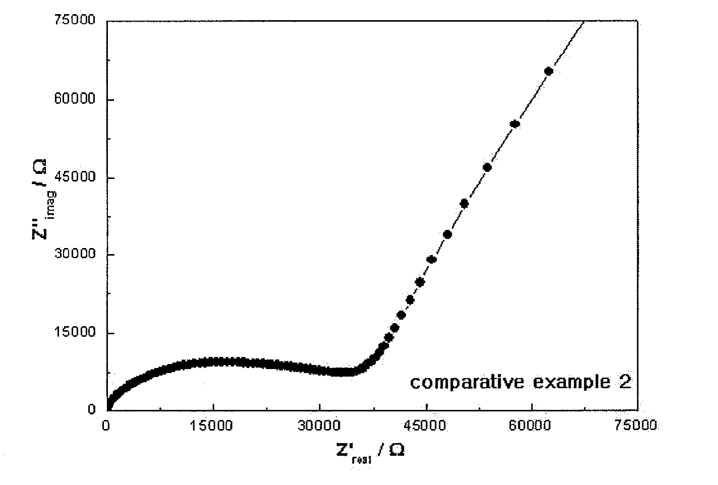
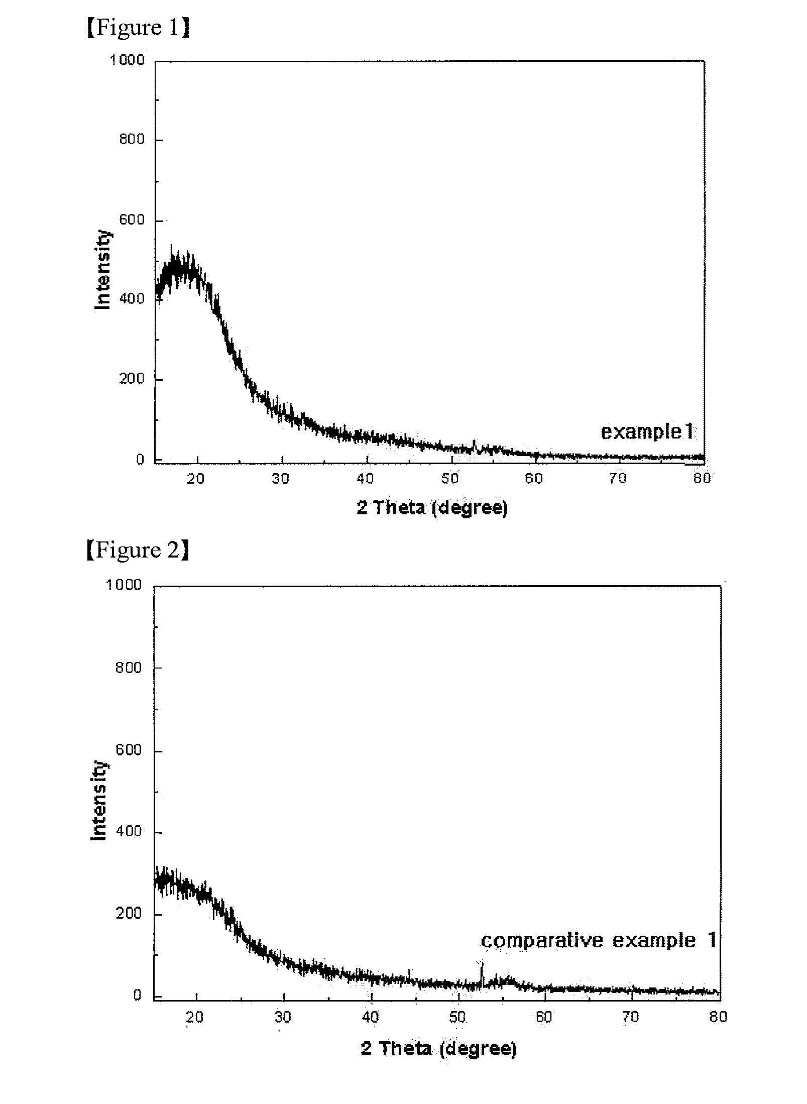
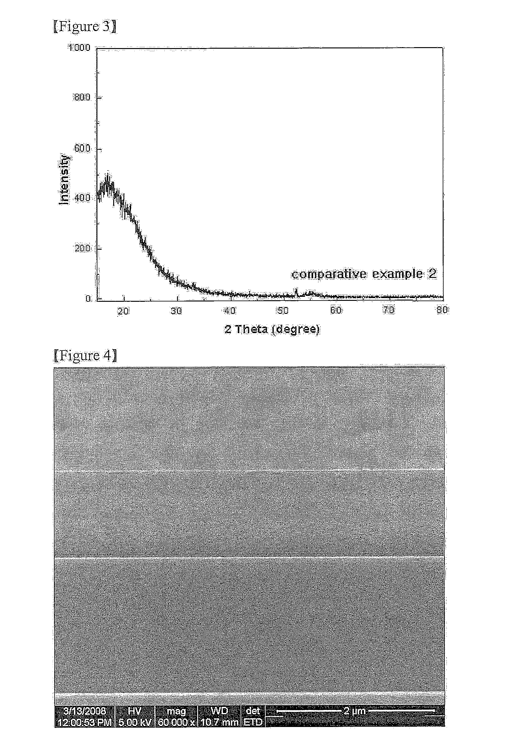
[0062] The X-ray diffraction (XRD) analysis results of Example 1, Comparative Example 1 and Comparative Example 2 are shown in FIGS. 1 to 3.

[0063] (2) SEM Image Analysis

[0064]FIG. 4 is a SEM image illustrating a cross-section of Example 1, and FIG. 5 is a SEM image illustrating a surface of Example 1.

[0065] With reference t...

example 2

Production of the Thin Film Battery

[0077] The platinum was formed on the Mica substrate having the thickness of 50 μm by using the cathode current collector by the DC sputtering in 2500 Å. Subsequently, after the cathode LiCoO2 was formed by the RF sputtering in 1 μm, the heat treatment was performed at the high temperature of 600° C. or more. The solid electrolyte of Example 1 was formed on the heat-treated cathode in 1 μm. Nickel was formed using the DC sputtering in 2,500 Å by the anode current collector on the position electrically insulated with the cathode current collector. Li was formed in 2 μm on the structure by using the thermal evaporation vacuum deposition to prepare Example 2 of the thin film battery.

experimental example 2

Performance Test of the Thin Film Battery

[0079]

[0080]FIG. 11 is a graph illustrating discharge characteristic of Example 2, and FIG. 12 is a graph illustrating discharge characteristic of Comparative Example 3.

[0081] With reference to FIGS. 11 to 12, in Example 2, even though the discharging was performed by using 10 times of current amount to the maximum, the capacity of about 90% was shown. On the other hand, in Comparative Example 3, when the discharging was performed by using 10 times of current amount to the maximum, the capacity of about 78% was shown. Through the results, it can be seen that the high rate discharge characteristic of Example 2 is very excellent.

[0082]

[0083]FIG. 13 is a SEM image illustrating a cross-section of the thin film battery of Example 2.

[0084]

[0085]FIG. 14 is an age change discharge graph of Example 2, and FIG. 15 is an age change discharge graph of Comparative Example 3. To be more specific, FIGS. 14 and 15 are discharging capacity result graphs i...


PUM

PropertyMeasurementUnit
temperatureaaaaaaaaaa
thicknessaaaaaaaaaa
temperatureaaaaaaaaaa

Abstract

The present invention relates to a solid electrolyte enables high ion conductivity, excellent voltage stability, low electric conductivity, homogeneous composition, reduced self-discharge and excellent atmosphere stability, a method of producing the same and a thin film battery comprising the same. The solid electrolyte according to the present invention is represented by the following formula. Lix—B—Oy—Nz  <Formula>

Description

TECHNICAL FIELD [0001] The present invention relates to a solid electrolyte, a method of producing the same, and a thin film battery comprising the same. More specifically, the present invention relates to a solid electrolyte that is represented by Lix—B—Oy—Nz, a method of producing the same, and a thin film battery comprising the same. BACKGROUND ART [0002] In accordance with the development of electronic and information communication industries, one carries personal terminals and office devices, etc. Thereby, in many technical fields such as cell phones, portable AV devices, and portable OA devices, the miniaturization of the devices is rapidly accomplished. However, as compared to the miniaturization and the portable trend of electronic devices, the size of electric power source is not relatively largely reduced. Accordingly, it is required that the energy density is increased to develop the lithium secondary battery having the excellent performance and the small size. [0003] Mea...

Claims


Application Information

Patent Timeline
Patent Type & Authority Applications(United States)
IPC IPC(8): H01M10/0562H01M10/04H01M10/36
CPCC23C14/0036C23C14/0676H01M6/40Y02E60/122H01M10/0525H01M10/0562H01M2300/0071H01M10/052Y02E60/10Y02P70/50H01M10/05H01M10/38
Inventor NAM, SANGCHEOLPARK, HOYOUNGLIM, YOUNGCHANGLEE, KICHANGAN, GEUNWANPARK, GIBACKHWANG, HOSUNGKIM, JIMIN
Owner APPLIED MATERIALS INC
Why Eureka
Try Eureka