Solid Electrolyte, Fabrication Method Thereof and Thin Film Battery Comprising the Same
a technology of solid electrolyte and fabrication method, which is applied in the direction of non-aqueous electrolyte cells, cell components, sustainable manufacturing/processing, etc., can solve the problems of easy production of batteries, limited miniaturization, and small size of electric power sources, and achieve low electric conductivity, high ion conductivity, and voltage stability
- Summary
- Abstract
- Description
- Claims
- Application Information
AI Technical Summary
Benefits of technology
Problems solved by technology
Method used
Image
Examples
experimental example 1
Performance Test of the Solid Electrolyte
[0053]
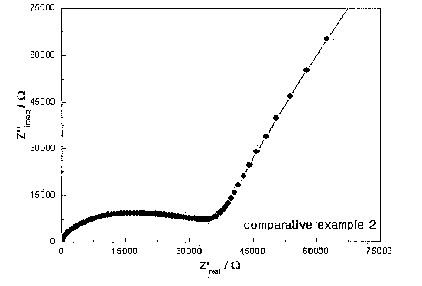
[0054]The relative ratio of the compositions obtained by the ICP-AES / ERD-TOF analysis results of Example 1 and Comparative Example 2 are described in Table 2.
TABLE 2ComparativeExample 1Example 2Li3.0990.903B1.0001.000O2.5320.658N0.5160.984Composition3.10:1.0:2.53:0.520.9:1.0:0.66:0.98(Li:B:O:N)
[0055]
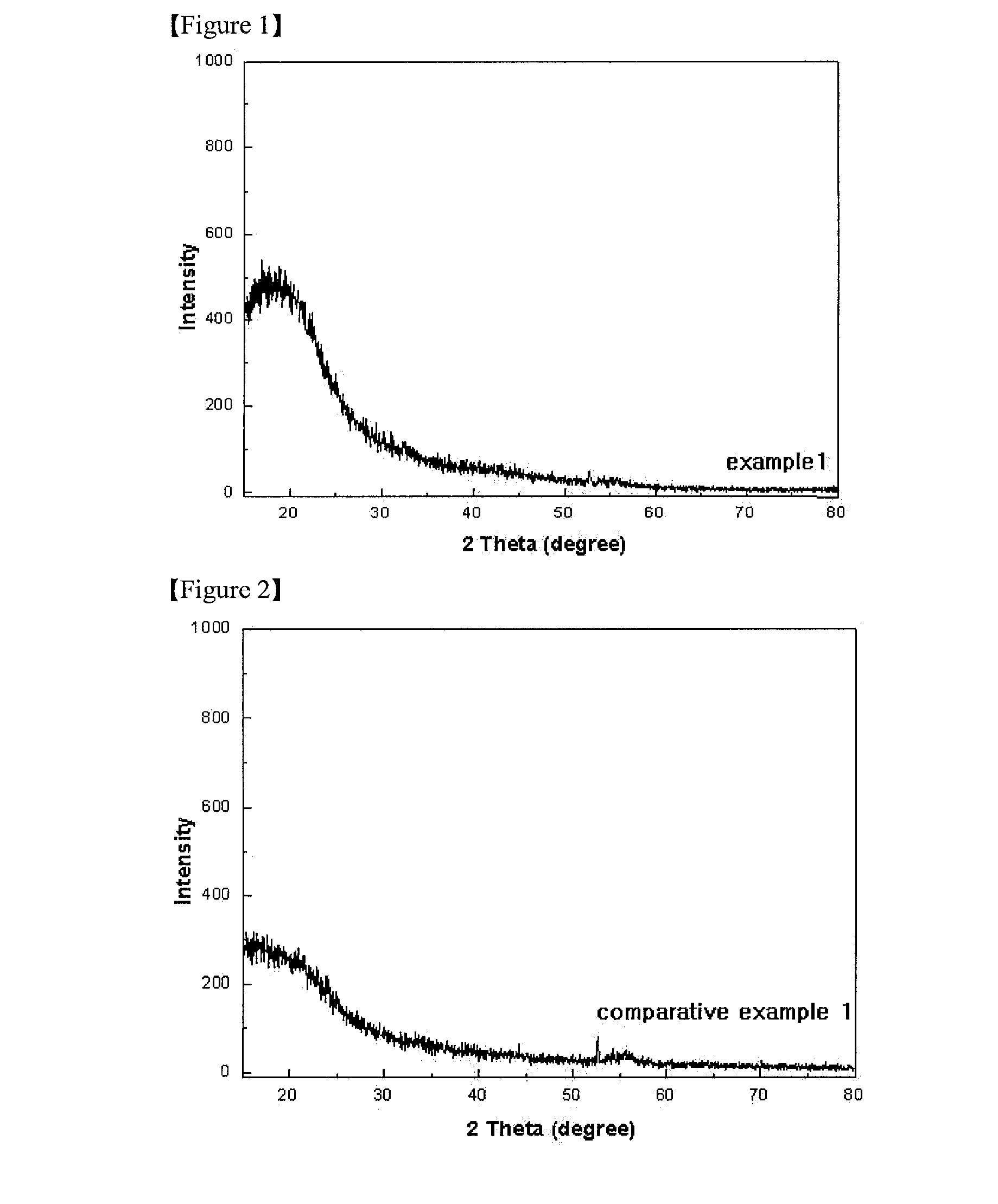
[0056](1) X-Ray Diffraction Analysis
[0057]Example 1, Comparative Example 1 and Comparative Example 2 were performed by using RINT / DMAS-2500 device under the following conditions.
[0058]X-ray: Cu Kα (λ=1.5406 Å)
[0059]Voltage-current: 40 V-30 mA
[0060]Measurement angle range: 15 to 80 Theta
[0061]Step: 0.02°
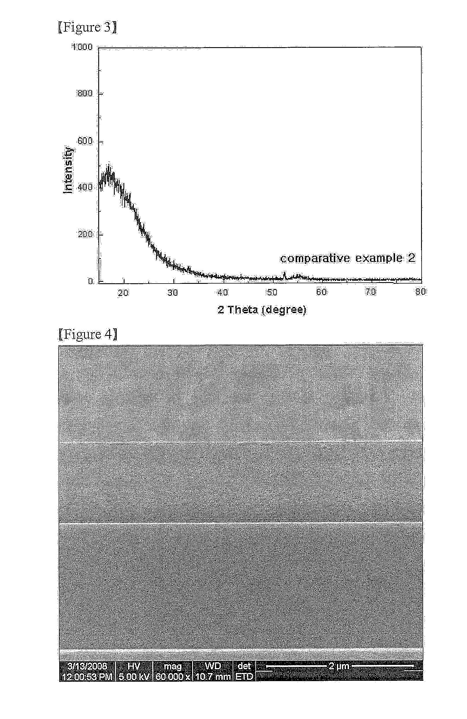
[0062]The X-ray diffraction (XRD) analysis results of Example 1, Comparative Example 1 and Comparative Example 2 are shown in FIGS. 1 to 3.
[0063](2) SEM Image Analysis
[0064]FIG. 4 is a SEM image illustrating a cross-section of Example 1, and FIG. 5 is a SEM image illustrating a surface of Example 1.
[0065]With reference to FIGS. 1 to 5, it can ...
example 2
Production of the Thin Film Battery
[0077]The platinum was formed on the Mica substrate having the thickness of 50 μm by using the cathode current collector by the DC sputtering in 2500 Å. Subsequently, after the cathode LiCoO2 was formed by the RF sputtering in 1 μm, the heat treatment was performed at the high temperature of 600° C. or more. The solid electrolyte of Example 1 was formed on the heat-treated cathode in 1 μm. Nickel was formed using the DC sputtering in 2,500 Å by the anode current collector on the position electrically insulated with the cathode current collector. Li was formed in 2 μm on the structure by using the thermal evaporation vacuum deposition to prepare Example 2 of the thin film battery.
experimental example 2
Performance Test of the Thin Film Battery
[0079]
[0080]FIG. 11 is a graph illustrating discharge characteristic of Example 2, and FIG. 12 is a graph illustrating discharge characteristic of Comparative Example 3.
[0081]With reference to FIGS. 11 to 12, in Example 2, even though the discharging was performed by using 10 times of current amount to the maximum, the capacity of about 90% was shown. On the other hand, in Comparative Example 3, when the discharging was performed by using 10 times of current amount to the maximum, the capacity of about 78% was shown. Through the results, it can be seen that the high rate discharge characteristic of Example 2 is very excellent.
[0082]
[0083]FIG. 13 is a SEM image illustrating a cross-section of the thin film battery of Example 2.
[0084]
[0085]FIG. 14 is an age change discharge graph of Example 2, and FIG. 15 is an age change discharge graph of Comparative Example 3. To be more specific, FIGS. 14 and 15 are discharging capacity result graphs in res...
PUM
| Property | Measurement | Unit |
|---|---|---|
| temperature | aaaaa | aaaaa |
| thickness | aaaaa | aaaaa |
| size | aaaaa | aaaaa |
Abstract
Description
Claims
Application Information
 - R&D
- Intellectual Property
- Life Sciences
- Materials
- Tech Scout
- Unparalleled Data Quality
- Higher Quality Content
- 60% Fewer Hallucinations
Browse by: Latest US Patents, China's latest patents, Technical Efficacy Thesaurus, Application Domain, Technology Topic, Popular Technical Reports.
© 2025 PatSnap. All rights reserved.Legal|Privacy policy|Modern Slavery Act Transparency Statement|Sitemap|About US| Contact US: help@patsnap.com


