
Corona igniter with magnetic screening

a technology of magnetic screening and igniter, which is applied in the direction of transformer/inductance details, spark plugs, electrical equipment, etc., can solve the problems of affecting the system carried on board a vehicle, or exceeding the threshold level, so as to limit the loss of eddy current and low loss

Active Publication Date: 2012-07-19
FEDERAL MOGUL MOTORPARTS LLC
View PDF36 Cites 36 Cited by
  • Summary
  • Abstract
  • Description
  • Claims
  • Application Information

AI Technical Summary

Benefits of technology

[0009]In another embodiment of the invention, there is a corona ignitor device configured to be fixed within a combustion chamber, including a housing extending between an upper end and a lower end of the ignitor device; inductor windings received in said housing between said upper and lower ends; and a magnetic shield located around the inductor windings to prevent magnetic flux from emanating out of the ignitor device.
[0011]In another aspect of the invention, the magnetic shield has a relatively high magnetic permeability with low electrical conductivity and encloses the inductor windings to prevent the magnetic flux from emanating out of the ignitor assembly.
[0013]In yet another aspect of the invention, the magnetic shield has low losses in the frequency range 500 KHz to 5 MHz and an electrical resistivity to at least limit eddy current losses.
[0014]As an alternative to the resin or gas, we may use a suitable oil or the inductor may be filled with mostly air and made physically large enough to avoid flashover.

Problems solved by technology

These fields may, in particular, disrupt systems carried on board a vehicle or exceed the threshold levels defined in emission standards.

Method used


Image

  • Corona igniter with magnetic screening
  • Corona igniter with magnetic screening
  • Corona igniter with magnetic screening

Examples


Embodiment Construction

[0025]Current designs of igniters for microwave or RF ignition systems for installation into the plug well of an engine suffer high loss and a reduction in inductance due to magnetic flux linking to the shield or conductive cylinder head, and create large eddy current losses. These issues are not easily avoided, as steps to reduce eddy current also reduce magnetic screening, allowing the magnetic field to penetrate further into the engine structure. This invention includes a magnetic flux inside the igniter body, thereby eliminating uncontrolled eddy current losses and changes in inductance.

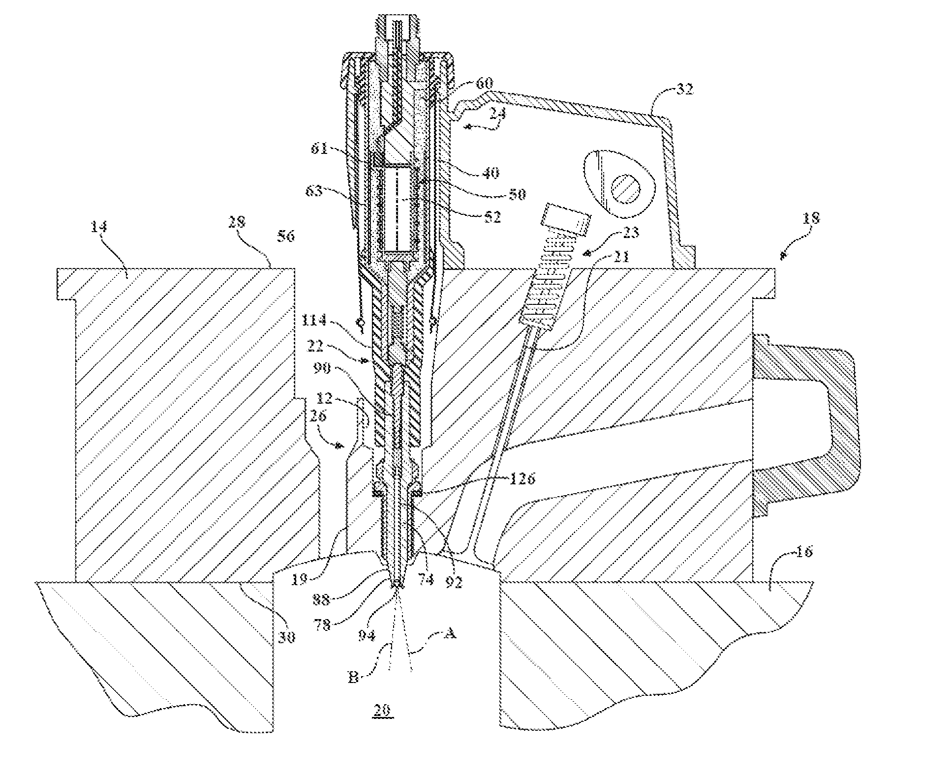
[0026]FIGS. 3-6 show an ignitor assembly, represented as a corona discharge ignitor assembly, and referred to hereafter as assembly 10, constructed in accordance with one aspect of the invention. FIG. 3 illustrates a cross-sectional view of an ignitor assembly according to the invention. The upper inductor subassembly 24 includes a plastic tubular housing 40 that extends along a first axis A′ bet...


PUM


Abstract

The invention relates to a corona ignitor device configured to be fixed within a combustion chamber, including a housing extending between an upper end and a lower end of the ignitor device. Inductor windings are received in the housing between the upper and lower ends, and a magnetic shield located between the housing and the inductor windings prevent magnetic flux from emanating out of the ignitor device.

Description

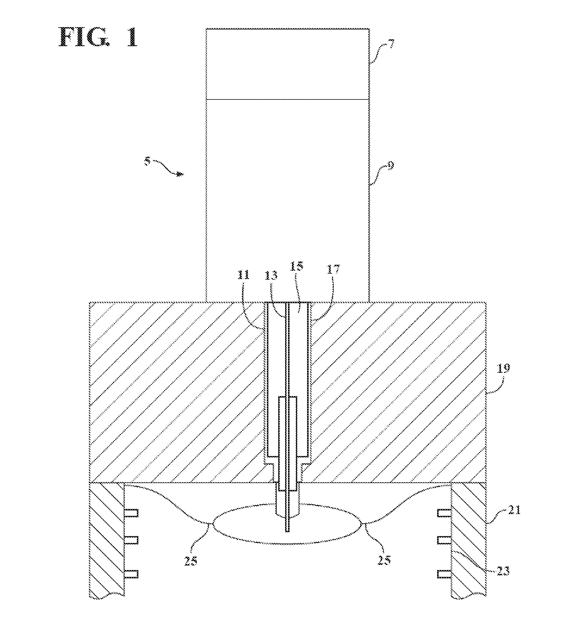
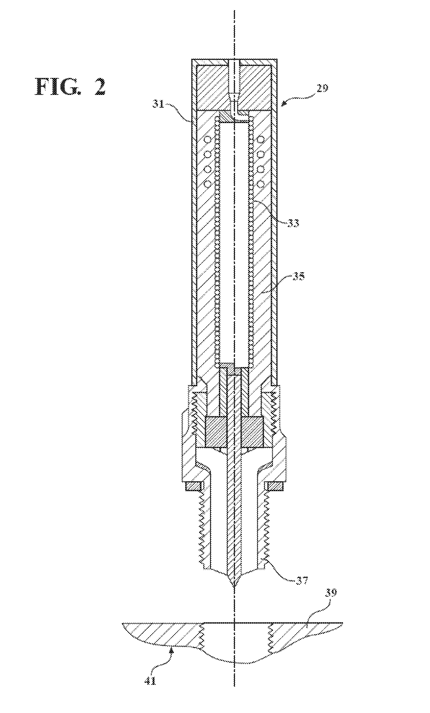
BACKGROUND OF THE INVENTION[0001]1. Technical Field[0002]This invention relates generally to ignitors used for igniting air / fuel mixtures in automotive application and the like.[0003]2. Related Art[0004]Conventional spark plugs generally utilize a ceramic insulator which is partially disposed within a metal shell and extends axially toward a terminal end. A conductive terminal is disposed within a central bore at the terminal end, where the conductive terminal is part of a center electrode assembly disposed within the central bore. At the opposite / spark forming end, the center electrode is disposed within the insulator and has an exposed sparking surface which together with a ground electrode disposed on the shell defines a spark gap. Many different insulator configurations are used to accommodate a wide variety of terminal, shell and electrode configurations.[0005]U.S. Pat. No. 6,883,507 discloses an ignitor for use in a corona discharge air / fuel ignition system. FIG. 1 is a diagra...

Claims


Application Information

Patent Timeline
Patent Type & Authority Applications(United States)
IPC IPC(8): H01T13/08
CPCH01F27/365H01T13/50H01T13/44H01F27/36H01F27/363H01F27/366
Inventor BURROWS, JOHN A.LYKOWSKI, JAMES D.
Owner FEDERAL MOGUL MOTORPARTS LLC
Learn More